Table of Contents
A drawing may describe the final shape of a fastener, but it does not describe everything required to manufacture that fastener reliably.
Before a non-standard fastener reaches mass production, manufacturers must translate its geometry, material, tolerances, functional requirements and annual volume into a repeatable production process.
That usually means answering a long list of questions.
Can the geometry be cold headed as drawn? Which dimensions actually control assembly performance? Does the component need machining after forming? How many forming stations are required? What will happen after heat treatment or plating? How should the part be inspected? And can the same process that produces ten successful samples remain stable when production reaches hundreds of thousands of pieces?
For buyers, sourcing engineers and product designers, understanding this development process makes supplier discussions much more productive.
It also explains why a successful custom fastener program is not simply:
Send drawing → Build tool → Start production
A more realistic sequence is:
Drawing → Requirement Review → DFM → Process Planning → Tooling → Trial Production → Sample Validation → Quality Approval → Mass Production
Each stage removes a different type of manufacturing risk.
How Does a Non-Standard Fastener Move From Drawing to Mass Production?
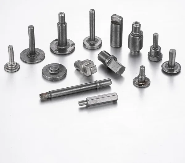
A typical custom fastener development project includes nine stages:
- RFQ and technical requirement review
- Drawing and functional analysis
- DFM and manufacturing feasibility review
- Process-route and cost development
- Tooling design and manufacturing
- Trial production and process adjustment
- Sample inspection and validation
- Production approval and quality planning
- Controlled mass production and continuous monitoring
The exact sequence varies by customer, application and industry.
An automotive program may require extensive PPAP documentation and production validation, while a general industrial component may follow a simpler approval process.
The principle is the same:
The goal is not just to prove that one acceptable part can be made. The goal is to prove that the process can continue making acceptable parts consistently.
Stage 1: The Development Process Starts With the RFQ
A good custom fastener project begins before tooling design.
It begins with good input information.
For a standard fastener, a recognized specification may already define much of what the manufacturer needs to know.
For non-standard fasteners, the supplier must understand much more about the specific application.
A useful RFQ should include, where available:
- Controlled 2D drawing
- 3D model
- Material specification
- Heat-treatment requirements
- Surface-treatment requirements
- Critical dimensions
- Thread specifications
- Mechanical-property requirements
- Expected annual volume
- Typical order quantity
- Application information
- Required quality documents
- Packaging requirements
- Target launch date
Romy’s guide on how to brief a custom cold-headed parts manufacturer before RFQ provides a more detailed checklist for preparing this information before quotation.
Why annual volume matters this early
Manufacturing engineers cannot optimize a process without knowing how frequently the part will be produced.
A project requiring 300 pieces may justify a very different process from one requiring 300,000 pieces every year.
For example, a low-volume prototype may be economically machined.
At higher repetitive volume, dedicated cold-heading tooling may justify a larger initial investment because the recurring manufacturing cost becomes more important.
This means quantity affects the process decision before the price is finalized.
Application information can be more valuable than another tolerance
Imagine a drawing for a stepped bolt with a precision shoulder.
Without context, the manufacturer only sees a diameter and tolerance.
If the buyer explains that:
“This shoulder rotates inside a bushing for the full service life of the product,”
the engineering team now understands why:
- Diameter matters
- Surface finish matters
- Roundness may matter
- Hardness may matter
- Wear behavior may matter
A strong supplier therefore reviews not only what the drawing says, but also what the part does.
Stage 2: Engineers Separate Shape From Function
The next stage is to determine which drawing requirements actually control product performance.
This sounds obvious, but it can be one of the most important parts of custom fastener development.
A drawing may contain 20 or 30 dimensions.
Only some may directly affect:
- Fit
- Sealing
- Alignment
- Rotation
- Torque transfer
- Bearing contact
- Clamp load
- Assembly depth
- Electrical contact
- Safety
These should receive the greatest engineering attention.
Critical dimensions influence the entire production strategy
Suppose a custom shaft contains four external diameters.
Three are simple clearance features.
The fourth fits into a bearing.
Treating all four diameters as equally critical could create unnecessary:
- Grinding
- CNC machining
- Inspection
- Sorting
- Tooling precision
A better development process identifies the functional diameter early and concentrates process capability where it creates value.
Romy’s custom bolt design checklist explains the same approach for bolt heads, shoulders, threads, materials and finishes.
Mating parts should be considered together
Custom fasteners do not function in isolation.
Their performance depends on the components around them.
Useful information may include:
- Mating-hole diameter
- Nut specification
- Bearing size
- Bushing dimensions
- Assembly clearance
- Installation torque
- Driver access
- Available envelope
- Required axial movement
A supplier that understands the assembly can often make better DFM recommendations than one that sees only an isolated fastener drawing.
Stage 3: DFM Determines Whether the Drawing Is Production-Friendly
Design for Manufacturing, or DFM, is where the drawing begins to become a manufacturing process.
The objective is not to redesign the customer’s product.
It is to identify features that create unnecessary forming difficulty, unstable production or avoidable cost before tooling exists.
For cold-headed parts, DFM may evaluate:
- Head-to-shank ratio
- Flange diameter
- Extrusion severity
- Hole depth
- Wall thickness
- Shoulder transitions
- Radii
- Recess geometry
- Long slender sections
- Material ductility
- Thread runout
- Tool accessibility
- Part ejection
- Tolerance requirements
Romy’s cold heading DFM design rules provide additional guidance on these manufacturability considerations.
Good DFM does not automatically simplify the part
Sometimes a complex feature is absolutely necessary.
If it performs an important function, the manufacturer should develop a process capable of producing it.
DFM becomes valuable when complexity provides no functional benefit.
For example, engineering may discover that:
- A sharp transition can use a radius
- A tolerance can be relaxed
- A machined surface can remain formed
- A washer can become an integral flange
- A separate sleeve can become part of the fastener
- A deep recess can be slightly redesigned to improve punch strength
These changes can improve both cost and production stability without changing how the finished assembly works.
DFM should happen before tooling approval
Once a customer approves tooling, geometry changes can mean:
- Die modification
- New punches
- New inserts
- New sample production
- Re-inspection
- Re-validation
The earlier a manufacturability issue is found, the cheaper it generally is to solve.
That is why supplier evaluation before tooling is so important. Romy’s guide to evaluating a custom fastener manufacturer before tooling explains the engineering, quality and capacity questions buyers should ask at this stage.
Stage 4: The Manufacturer Builds the Complete Process Route
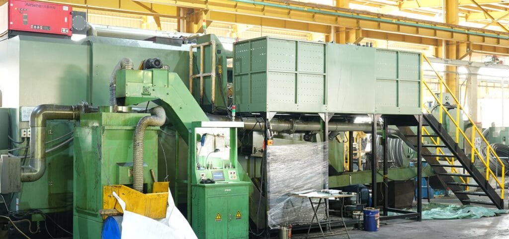
Once the geometry is considered manufacturable, the supplier determines how the part will actually be produced.
A custom fastener may follow a route such as:
Wire → Cutoff → Cold Heading → Thread Rolling → CNC Machining → Heat Treatment → Surface Treatment → Inspection → Packaging
Another part may need only:
Wire → Cold Heading → Thread Rolling → Inspection
These are very different cost structures.
What should be cold formed?
For suitable parts, cold heading can create features such as:
- Heads
- Flanges
- Shoulders
- Collars
- Stepped shafts
- Pilot sections
- Hollow features
- Recesses
- Polygonal forms
- Near-net external geometry
The more useful geometry created directly during forming, the less material may need to be removed afterward.
What should remain a secondary operation?
Not every feature should be forced into the cold-heading process.
Secondary machining may remain the better solution for:
- Very precise local diameters
- Cross holes
- Off-axis features
- Certain deep holes
- Tight bearing journals
- Sharp internal geometry
- Features requiring fine surface finish
A good custom fastener manufacturer does not try to prove that cold heading can replace every other process.
The manufacturer identifies the most economical and stable combination of processes.
Romy’s comparison of cold heading manufacturing vs CNC machining explains when cold forming, machining or a hybrid route makes the most sense.
The cheapest route on paper is not always the cheapest route in production
Suppose Process A requires:
- Simpler tooling
- Three CNC operations per part
Process B requires:
- More sophisticated multi-station tooling
- One small finishing operation
For 500 parts, Process A may be more economical.
For 500,000 parts, the recurring machining time can completely change the calculation.
This is why process design should reflect the expected lifetime production volume.
Stage 5: Tooling Turns the Process Plan Into Physical Reality
For custom cold-headed components, tooling is not merely a fixture.
The punches and dies control how material flows from wire into the finished geometry.
Tool design may need to account for:
- Material volume
- Number of forming stages
- Upsetting
- Forward extrusion
- Backward extrusion
- Reduction ratios
- Punch support
- Die inserts
- Ejection
- Alignment
- Tool steel
- Heat treatment
- Surface treatment
- Wear areas
- Spare tooling
Romy’s Cold Heading Die Design guide explains the relationship between tooling geometry, tool wear and finished-part accuracy.
Complex parts are rarely formed in one dramatic step
Consider a large flanged component.
Trying to move all required material into the finished flange in one operation can create excessive forming load or poor material flow.
A multi-station process may gradually create:
- Preform
- Intermediate upset
- Final flange
- Additional extrusion or calibration
Each station prepares the material for the next.
The tooling engineer is therefore planning a sequence of controlled deformation, not merely reproducing the final CAD shape.
Tooling development should consider production life
A tool that successfully makes 100 samples is not automatically a good production tool.
Engineers also need to think about:
- Expected tool life
- Wear location
- Maintenance
- Replaceable inserts
- Spare punches
- Tool-change time
- Dimensional drift as tools wear
This becomes increasingly important in high-volume production.
Stage 6: Trial Production Tests the Manufacturing Concept
After tooling is built, the process enters trial production.
This is where engineering assumptions meet real material, real machines and real tooling.
The first acceptable part is useful.
It is not the final objective.
Trial production may reveal issues such as:
- Incomplete die filling
- Laps
- Cracks
- Excessive flash
- Dimensional drift
- Punch marks
- Surface defects
- Ejection problems
- Tool interference
- Poor material flow
- Straightness variation
The engineering team then adjusts the process.
Trial production is an engineering loop
A typical loop may look like:
Run → Measure → Diagnose → Adjust → Run Again
Adjustments may involve:
- Tool dimensions
- Machine setup
- Lubrication
- Material condition
- Forming sequence
- Punch position
- Die alignment
- Cutoff volume
This is why an experienced tooling and production team can be more valuable than an impressive first quotation.
The challenge is not only making the geometry possible.
It is creating a process that is stable enough to repeat.
Stage 7: Samples Must Prove More Than Appearance
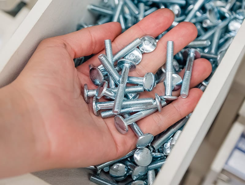
Customers often focus heavily on the first samples.
That makes sense because samples are the first physical proof of the new component.
But sample approval should answer several different questions.
Does the part match the drawing?
Inspection may verify:
- Overall dimensions
- Threads
- Critical diameters
- Head geometry
- Shoulders
- Profiles
- Holes
- Runout
- Surface condition
Does the part work in the actual assembly?
A dimensionally acceptable component can still fail functionally.
Assembly testing may reveal:
- Poor insertion
- Unexpected interference
- Excess movement
- Driver problems
- Incorrect clamp condition
- Poor mating with another component
This is why functional testing is valuable for application-specific parts.
Does the material meet the requirement?
Depending on the project, validation may include:
- Material certificates
- Hardness
- Mechanical testing
- Coating inspection
- Corrosion testing
- Special customer requirements
Is the sample production-intent?
This question is extremely important.
A CNC-machined prototype can prove that the geometry works.
It does not automatically prove that the final cold-heading process works.
Production-intent samples should represent the actual process as closely as required by the program.
That may include the intended:
- Raw material
- Tooling
- Cold-heading machine
- Thread process
- Heat treatment
- Coating
- Inspection method
The closer the sample is to future production, the more meaningful the validation becomes.
Stage 8: Automotive Programs May Require PPAP and Core Tools
For general industrial components, customer approval may be based on samples, dimensional reports and material documentation.
Automotive projects can require a more formal approval structure.
The Automotive Industry Action Group’s Production Part Approval Process (PPAP) is designed to demonstrate that engineering design requirements can be consistently met during an actual production run at production rates.
Depending on customer requirements, a PPAP submission can involve documents or records associated with areas such as:
- Design records
- Process flow
- PFMEA
- Control Plan
- Measurement-system analysis
- Dimensional results
- Material or performance results
- Initial process studies
- Sample parts
- Production approval records
The exact submission level and customer-specific requirements should always be confirmed for the individual program.
PPAP is not simply paperwork added after the parts are finished
The important concept behind PPAP is process confidence.
The buyer is effectively asking:
“Can this supplier produce the approved part repeatedly under real production conditions?”
That question affects process design from the beginning.
AIAG groups PPAP with other automotive Quality Core Tools used to support structured product and process development.
For automotive suppliers operating under IATF requirements, the official International Automotive Task Force publications currently list IATF 16949:2016 as the automotive quality management system standard, together with the current recognition rules and related publications.
Romy states that its manufacturing system is IATF 16949 certified and provides full-process support for custom cold-headed components from tooling through mass production.
Stage 9: Mass Production Is Where Process Capability Matters Most
Sample approval is not the end of custom fastener development.
It is the beginning of production control.
Once mass production starts, new variables appear.
Tools wear.
Raw-material lots change.
Heat-treatment batches change.
Machines run for longer periods.
Operators and production shifts change.
Order quantities increase.
The manufacturing process therefore needs controls that detect variation before it becomes a customer problem.
Critical characteristics need a control strategy
Depending on the component and customer requirements, control methods may include:
- First-piece inspection
- In-process inspection
- Patrol inspection
- Functional gauges
- Thread gauges
- Optical measurement
- CMM inspection
- Hardness testing
- Automatic sorting
- Statistical process monitoring
The correct approach depends on the risk associated with the feature.
Tool wear should be treated as predictable process behavior
Suppose a critical diameter gradually increases as a die insert wears.
Waiting until the dimension exceeds specification means the process has already lost control.
A stronger strategy identifies:
- Normal wear trend
- Inspection frequency
- Maintenance point
- Tool-change limit
The objective is preventive control rather than reactive sorting.
Traceability becomes increasingly important
For many industrial and automotive programs, buyers need to connect finished parts back to:
- Material lot
- Production batch
- Heat-treatment batch
- Coating batch
- Inspection results
- Production date
Traceability makes root-cause analysis much faster if a problem appears later.
General quality-management principles also emphasize controlled processes, consistent output and continual improvement. The current published ISO 9001:2015 quality management standard remains the widely recognized general QMS reference while ISO’s next edition is being finalized for publication.
From Sample Approval to Stable Production: What Changes?
The transition from sampling to mass production is often underestimated.
| Development Stage | Main Question | Typical Focus |
|---|---|---|
| Drawing review | What does the part need to do? | Function and specifications |
| DFM | Can it be manufactured reliably? | Geometry and material |
| Process planning | What is the best manufacturing route? | Cold heading vs secondary processes |
| Tooling | How will material be formed? | Punches, dies and sequence |
| Trial run | Does the process physically work? | Filling, defects and dimensions |
| Sample validation | Does the part meet requirements? | Inspection and assembly |
| Production validation | Can it repeat at rate? | Process capability |
| Mass production | Can quality remain stable? | Control, tool wear and traceability |
This distinction is important.
A supplier that is excellent at prototype machining is not automatically excellent at mass production.
A supplier that can cold head a difficult geometry once is not automatically capable of maintaining it for millions of cycles.
The development process must prove both the part and the process.
What Usually Causes a Custom Fastener Project to Go Wrong?
Problems are often blamed on tooling.
In reality, many begin earlier.
Incomplete RFQ information
If the supplier does not know:
- Annual volume
- Critical dimensions
- Application
- Coating
- Quality requirements
the original process and quotation may be built on incorrect assumptions.
Design changes after tooling
A seemingly small change to:
- Shoulder diameter
- Flange size
- Hole depth
- Material
- Thread length
can require a tooling change.
Drawing revisions therefore need formal control.
Prototype process differs too much from production
A beautifully machined prototype proves geometry.
It may say little about production cold heading.
The closer the approval part is to the final process, the more useful the validation.
Critical tolerances are discovered too late
Manufacturers need to know which dimensions deserve the strongest process controls before tooling and inspection methods are finalized.
Coating or heat treatment was not included in dimensional planning
A diameter can meet specification before coating and interfere afterward.
A long shaft can be straight before heat treatment and move after thermal processing.
The process route must consider the final finished condition.
Production volume changes dramatically
A tool and process developed for 20,000 pieces per year may need a different maintenance and capacity strategy if demand increases to 500,000.
What Should Buyers Review Before Approving Mass Production?
Before giving final production approval, check five areas.
1. Drawing status
Confirm:
- Correct revision
- Material
- Finish
- Thread specification
- Critical dimensions
- Customer notes
2. Process status
Confirm:
- Tooling is production-intent
- Manufacturing route is defined
- Secondary operations are approved
- Heat-treatment route is fixed
- Coating supplier/process is approved where required
3. Inspection status
Confirm:
- Critical dimensions have inspection methods
- Gauges are available
- Sampling frequency is established
- Functional testing is defined
- Records meet customer requirements
4. Capacity status
Confirm:
- Expected monthly output
- Tool life
- Spare tooling
- Machine availability
- Peak demand capability
5. Quality-document status
Where applicable, confirm:
- Material certificates
- Dimensional reports
- Control Plan
- PFMEA
- Capability data
- PPAP
- Traceability
This prevents the common situation where the product is technically approved but the production system is not yet ready.
A Better Way to Think About Custom Fastener Development
Buyers sometimes view custom fastener development as a linear purchasing activity:
Send RFQ → Receive Quote → Approve Sample → Buy Parts
From an engineering perspective, it is better understood as a risk-reduction process.
RFQ removes specification uncertainty
Everyone agrees on what must be produced.
DFM removes manufacturability uncertainty
The supplier determines whether geometry, material and tolerance make sense for the selected process.
Tooling removes process-design uncertainty
The proposed forming sequence becomes a physical production system.
Sampling removes part-performance uncertainty
The component is inspected and tested.
Production validation removes repeatability uncertainty
The supplier demonstrates that the process can continue meeting requirements.
Mass-production controls reduce long-term variation
Tool wear, material batches and other variables are monitored.
This is why a reliable custom fastener manufacturer should be involved earlier than the final purchasing stage.
What Does Romy’s Development Process Cover?
Romy’s Custom Cold Heading Solutions describe a full-cycle process covering requirement analysis, design and quotation, sampling, production, quality inspection and delivery. The company’s current product scope includes non-standard sleeves and bushings, special-shaped shafts, gear splines, polygonal components, long-rod bolts and other drawing-based cold-headed parts.
According to Romy’s current website, its manufacturing base uses 23 multi-station cold-heading machines, supports in-house mold development and has a stated daily production capacity above 1.2 million pieces.
Those capabilities matter most when they are connected into one controlled process:
Engineering review → Tool development → Trial production → Inspection → Mass production
Equipment alone does not create a good custom component.
The value comes from how engineering, tooling, production and quality control work together.
Frequently Asked Questions
How long does it take to develop a non-standard fastener?
There is no universal lead time.
Development depends on:
- Part complexity
- Material availability
- Tooling complexity
- Number of forming stations
- Secondary operations
- Heat treatment
- Coating
- Sample revisions
- Validation requirements
A simple customized bolt and a complex multi-station spline shaft may require very different development processes.
What information should I send before requesting a custom fastener quote?
Ideally provide a controlled 2D drawing, 3D model where available, material, tolerances, heat treatment, finish, annual demand, order quantity, application information and quality-document requirements.
The more complete the RFQ, the more accurately the manufacturer can select a production route.
Why does a custom fastener manufacturer need annual volume?
Annual volume affects tooling investment, machine selection, cycle economics, tool-life planning and whether cold heading or machining is the most economical production process.
Is a prototype the same as a production sample?
Not always.
A prototype may be CNC machined only to verify fit and function. A production-intent sample should represent the actual or intended manufacturing process much more closely.
When should DFM happen?
Ideally before tooling approval.
DFM performed after production tooling is complete may identify valid improvements, but those changes become more expensive to implement.
Can non-standard fasteners combine cold heading and CNC machining?
Yes.
Many precision components use cold heading to create the primary near-net shape and CNC machining only where special holes, tight tolerances or other features require material removal.
What is PPAP in custom fastener manufacturing?
PPAP stands for Production Part Approval Process. In automotive supply chains, it is used to demonstrate that a supplier understands the design requirements and that the production process can consistently produce conforming parts under actual production conditions. AIAG publishes the official PPAP reference.
Does every custom fastener require PPAP?
No.
PPAP is particularly associated with automotive customer requirements. Other industrial customers may request different documentation, such as dimensional reports, material certificates, inspection records or first-article approval.
Why can a sample pass inspection while mass production still has problems?
Sampling occurs over a relatively small number of parts and often with new tools and close engineering attention. Mass production introduces tool wear, material-lot variation, longer machine runs and larger quantities. Production validation must therefore evaluate process repeatability, not only individual sample dimensions.
How can buyers reduce development risk?
The most effective steps are:
- Provide complete requirements early
- Identify critical dimensions
- Share realistic annual volume
- Request DFM before tooling
- Confirm the production route
- Validate production-intent samples
- Define quality documents before quotation
- Control drawing revisions
- Confirm mass-production capacity
From a Drawing to a Repeatable Production Process
The drawing is where a custom fastener begins.
It is not where engineering ends.
To reach stable mass production, the manufacturer must convert that drawing into:
- A forming strategy
- A tooling system
- A material specification
- A secondary-process route
- An inspection plan
- A quality-control system
- A repeatable production cycle
That is the real difference between making a part and industrializing a part.
A successful non-standard fastener project should prove three things:
The geometry works.
The manufacturing process works.
The process can keep working as production volume increases.
If you are developing a non-standard bolt, shaft, sleeve, bushing, spline or other cold-headed precision component, explore Romy’s custom cold heading capabilities or send your drawing, material and production requirements to the Romy engineering team for an early manufacturability review before tooling and mass production.