
Table of Contents
Standard screws solve an enormous number of fastening problems efficiently. Their dimensions, head styles, drives and threads are already established, which simplifies design, sourcing, inspection and replacement.
The problem begins when the product is not designed around a standard fastening envelope.
A motor housing may provide almost no head clearance. An electrical assembly may leave insufficient space for a conventional driver. A mechanism may need the screw to locate another component as well as fasten it. An automated production line may require a screw that feeds in only one orientation. A compact device may have room for the thread but not the standard head.
In these situations, engineers sometimes redesign the surrounding components simply to make a catalog screw fit.
That is not always the best solution.
Well-designed custom made screws can adapt the fastener to the product rather than forcing the product to adapt to the fastener. The key is to customize only the geometry that solves a real engineering problem while retaining standardized threads, materials or mechanical requirements wherever they remain useful.
This guide examines eight practical design strategies for tight installation spaces and explains how head geometry, drive selection, shoulders, pilots and integrated features can influence manufacturability, assembly and long-term production.
When Does a Standard Screw Become the Wrong Fit?
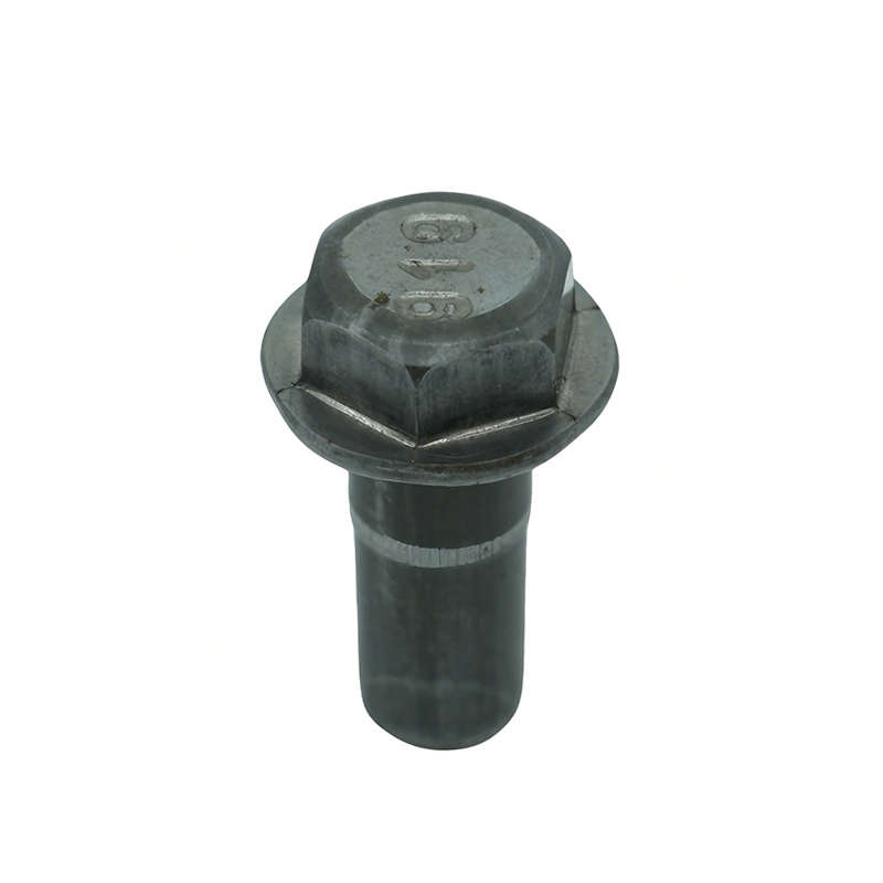
A standard screw should normally remain the first option when it satisfies the application without creating additional problems.
Recognized specifications such as ASME B18.6.3 establish dimensional requirements for many common machine screws, tapping screws and metallic drive screws in inch series. Using standardized hardware can provide clear benefits in interchangeability and sourcing.
Customization becomes worth evaluating when the standard screw causes secondary problems such as limited tool access, interference with nearby components, unnecessary assembly steps or additional hardware.
Typical warning signs include a screw that technically fits the thread but requires the housing to be enlarged, a head that interferes with a moving component, an operator who cannot reach the drive straight-on, or an assembly that requires separate washers, sleeves or locating pins because the screw cannot perform those functions itself.
The question should therefore be:
Does the standard screw fit the complete manufacturing and assembly system, not just the threaded hole?
Eight Custom Screw Design Options at a Glance
| Design Option | Main Problem It Solves | Key Engineering Consideration |
|---|---|---|
| Low-profile head | Limited vertical clearance | Head strength and drive depth |
| Reduced head diameter | Limited radial space | Bearing area and tightening load |
| Countersunk geometry | Flush surface required | Countersink alignment and head loadability |
| Internal drive | Limited external wrench access | Punch strength and driver engagement |
| Shoulder section | Location, spacing or pivot function | Diameter, length and surface finish |
| Pilot or lead feature | Difficult alignment | Insertion geometry and forming feasibility |
| Anti-rotation feature | Screw turns during assembly | Mating geometry and orientation |
| Integrated flange/function | Extra washer or spacer required | Forming severity and total part geometry |
These options can also be combined.
For example, one non standard screw may use a low-profile head, internal drive and precision shoulder together because each feature solves a different assembly problem.
1. Use a Low-Profile Head When Vertical Clearance Is Limited
One of the most common packaging problems is simply not having enough space above the screw.
A standard head may interfere with:
- A cover
- Moving linkage
- Adjacent shaft
- Electronic component
- Housing wall
- Decorative surface
The first response is often to reduce head height.
That can work, but the decision has consequences.
Lower head height changes more than appearance
A screw head has to provide enough material to support the drive feature and transfer installation load.
As the head becomes thinner, the designer must consider the relationship between:
- Head height
- Head diameter
- Drive depth
- Material
- Tightening requirement
- Tool strength
A very thin head combined with a deep internal drive can leave too little material between the drive recess and the bearing surface.
For reference, ISO 7380-1:2022 covers hexagon socket button-head screws and explicitly recognizes reduced loadability associated with this type of reduced-head geometry.
That illustrates an important principle for custom design:
Reducing head size can solve packaging problems, but head geometry and mechanical requirements must still be considered together.
When a low-profile custom head is useful
This option can be appropriate for:
- Compact mechanical assemblies
- Appliance mechanisms
- Electrical equipment
- Automotive interiors
- Thin housings
- Moving mechanisms with limited clearance
The drawing should clearly define the maximum allowable installation height rather than simply requesting “the thinnest possible head.”
That gives the manufacturer room to balance clearance and manufacturability.
2. Reduce Head Diameter When Radial Space Is the Constraint
Sometimes vertical clearance is adequate, but the screw head interferes with surrounding features sideways.
A conventional screw may sit too close to:
- Housing walls
- Adjacent fasteners
- Bearings
- Electrical terminals
- Molded ribs
- Other moving components
Reducing head diameter can create the required radial clearance.
However, head diameter also influences the bearing surface under the screw.
Smaller is not automatically better
A smaller head can reduce available bearing area.
Depending on the joint, that may increase contact pressure against:
- Plastic
- Aluminum
- Sheet metal
- Soft coatings
If the standard head diameter is larger than necessary, reducing it can be straightforward.
If the application relies on the head to distribute clamp load over a soft surface, the change deserves more careful evaluation.
Think about the mating surface
Before changing head diameter, define:
- Material under the head
- Thickness of the mating component
- Required clamp load
- Washer usage
- Risk of pull-through
- Available radial envelope
In some assemblies, the most efficient solution is not simply a smaller head. It may be a custom head with an asymmetric or application-specific profile designed around the surrounding components.
For drawing-based parts where standard fastener geometry cannot meet the assembly envelope, Romy’s Custom Cold Heading Solutions cover special-shaped cold-headed components developed around specific functional requirements.
3. Use Countersunk Geometry When the Surface Must Remain Flush
A countersunk screw moves much of the head into the mating component rather than leaving it above the surface.
This can be useful when:
- Another component slides over the surface
- Exterior appearance matters
- The assembly needs a flush profile
- Head projection creates interference
- Space above the joint is extremely restricted
However, countersunk geometry introduces a different set of engineering considerations.
The head and mating countersink work together
A countersunk screw does not create a useful flush condition by itself.
Its head angle and the mating countersink need to align properly.
Poor alignment can produce uneven bearing contact and undesirable loading.
The current ISO 10642:2026 standard for hexagon socket countersunk head screws specifically highlights both the reduced loadability associated with this head design and the importance of alignment between the head and countersunk bearing surface.
That makes countersunk screws a good example of why packaging geometry and structural performance need to be considered together.
Questions to review
Before using custom countersunk geometry, determine:
- Required head angle
- Maximum head diameter
- Available material thickness
- Countersink depth
- Driver size
- Tightening load
- Required flushness
- Mating material
If the surrounding component is very thin, there may not be enough material to support a large countersink.
In that case, a reduced-profile head may be more appropriate.
4. Change the Drive When External Tool Access Is Restricted
A standard external hex head requires access around the outside of the fastener.
That space may not exist in a compact product.
An internal drive can reduce radial installation clearance because the tool engages inside the head rather than around it.
Possible drive concepts include:
- Internal hex
- Hexalobular socket
- Cross recess
- Slot
- Custom internal geometry
The drive should be selected according to the actual installation process rather than habit.
Driver access is a three-dimensional problem
Engineers should check:
- Radial clearance
- Axial access
- Driver insertion depth
- Tool angle
- Tightening torque
- Automation method
A drive may fit within the available diameter but still be difficult to reach because the tool cannot approach the screw straight-on.
Drive depth affects cold-heading tooling
Internal drive features are commonly created using a punch during forming.
A deeper recess generally requires a longer or more highly loaded punch feature.
That can influence:
- Punch strength
- Tool wear
- Risk of punch breakage
- Material filling
- Head thickness
For this reason, asking for the deepest possible recess is not automatically good design.
The drive only needs enough geometry to transmit the required installation torque reliably.
Romy’s technical guide to cold heading die design explains how punch geometry, tool support and material flow influence both tooling life and finished-part accuracy.
5. Add a Shoulder When the Screw Must Also Locate or Space Components
One of the most valuable forms of customization is adding an unthreaded shoulder between the head and thread.
A shoulder can allow one screw to perform several functions simultaneously.
It may provide:
- Component location
- Controlled spacing
- Pivot surface
- Bearing surface
- Stop position
- Guided movement
This can eliminate separate spacers or sleeves.
Shoulder diameter should come from the mating component
Do not select a shoulder diameter only because it is convenient to manufacture.
Start with the functional relationship.
Ask:
- What hole does the shoulder enter?
- Is movement required?
- Is the fit clearance or interference?
- Does anything rotate around it?
- Does the shoulder carry load?
- Is surface finish important?
A shoulder that only maintains spacing may tolerate more variation than a shoulder used as a bearing journal.
Shoulder length can control the whole assembly
In compact mechanisms, shoulder length may determine exactly how far two parts can approach one another.
That makes the shoulder a critical dimensional feature rather than a cosmetic one.
If the tolerance is very tight, the manufacturer may need to consider:
- Cold-heading capability
- Calibration
- CNC finishing
- Grinding
- Inspection method
A hybrid route can sometimes be more stable than trying to create every precision feature in a single process.
For more information on choosing the right process combination, Romy’s guide to cold heading manufacturing vs CNC machining explains where near-net-shape forming and secondary machining can complement each other.
6. Add a Pilot or Lead Feature When Alignment Is Difficult
Compact assemblies often leave very little space for operators or automated equipment to correct misalignment.
If a screw has to enter:
- Several stacked holes
- A recessed threaded feature
- A moving bracket
- An automated fixture
a pilot or lead feature can make assembly easier.
What a pilot can do
A properly designed pilot may help:
- Center the screw before thread engagement
- Align stacked components
- Reduce cross-threading risk
- Improve automated insertion
- Guide the part into a hidden hole
This can be especially useful when the screw cannot easily be seen during installation.
The pilot should solve a defined problem
A pilot adds length and geometry.
If there is no alignment difficulty, the feature may add complexity without adding value.
The design should therefore define:
- Pilot diameter
- Pilot length
- Tip geometry
- Relationship to thread diameter
- Available insertion depth
- Mating-hole size
An excessively long pilot may interfere with internal components.
An excessively small pilot may provide little alignment benefit.
The correct geometry comes from the actual assembly.
7. Add an Anti-Rotation Feature When the Screw Cannot Be Held From Both Sides
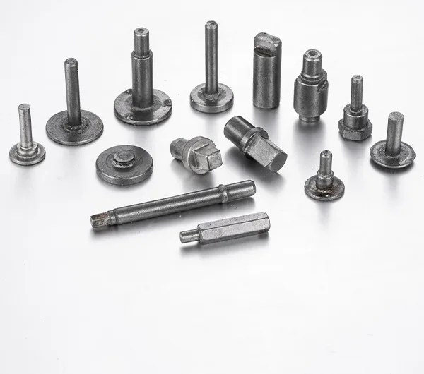
Some assemblies provide installation access from only one side.
If the screw rotates while another component is tightened, assembly can become difficult.
A non-standard screw can incorporate geometry that reacts against the mating component.
Possible features include:
- Flats
- Square sections
- Polygonal sections
- Tabs
- Special under-head geometry
- Serrated or formed features where appropriate
This can allow the product itself to resist rotation.
Anti-rotation geometry can remove an assembly operation
Consider a joint where one operator must hold the screw head while another tool tightens the nut.
If the screw includes a feature that locks into the surrounding structure, the holding operation may disappear.
That can improve:
- Assembly access
- Cycle time
- Automation
- Repeatability
However, the mating component must be designed to react against that feature.
A square section does little if it sits inside a large round clearance hole.
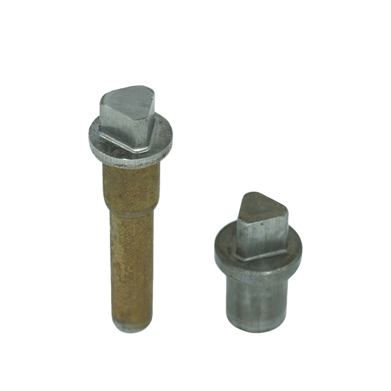
Cold heading can create functional non-round geometry
Cold forming is not limited to conventional round bolt shapes.
Depending on geometry and material, polygonal or special-shaped sections can sometimes be formed directly.
For example, Romy’s Power Tool Quick Clamp Core Shaft uses cold-headed two-flat and internal-hole geometry in a functional mechanical component, illustrating how shaped features can be integrated into a cold-formed part rather than added solely through later machining.
The important point is not to copy a particular geometry.
It is to recognize that the fastener can sometimes interact mechanically with its mating structure.
8. Integrate the Washer, Spacer or Stop Feature Into the Screw
Tight assemblies often become crowded because the screw is only one of several small parts installed at the same location.
The joint may require:
- Screw
- Washer
- Spacer
- Sleeve
- Stop feature
Each component occupies space and must be handled during assembly.
A custom screw can sometimes integrate one or more of these functions.
Integral flange
A formed flange may provide a larger bearing area and potentially remove a separate washer.
Controlled shoulder
A shoulder may replace a spacer or sleeve.
Stop geometry
A formed step may limit insertion depth or define component position.
Locating feature
An additional diameter may guide the screw or align another part.
This creates a more complex fastener but potentially a simpler product.
Evaluate total assembly complexity
A standard screw costing less per piece does not automatically create the lowest-cost assembly if it requires three additional components and multiple installation steps.
The engineering team should compare:
Standard hardware system
with:
Integrated custom component
Romy’s practical guide to custom cold-headed fasteners explains how custom geometry can be used when standard bolts, screws, pins or rivets cannot satisfy specific assembly requirements.
How to Choose Between the Eight Design Options
The right design depends on what type of space is actually limited.
| Design Constraint | First Option to Evaluate |
|---|---|
| Not enough height above screw | Low-profile head |
| Not enough space around head | Reduced head diameter |
| Surface must remain completely flush | Countersunk head |
| Wrench cannot fit around head | Internal drive |
| Screw must locate or space another part | Shoulder |
| Screw is difficult to align | Pilot or lead feature |
| Screw rotates during installation | Anti-rotation geometry |
| Too many small components at joint | Integrated flange/shoulder/stop |
A compact screw may use more than one strategy.
For example, an assembly may require:
reduced head + internal drive + locating shoulder
The manufacturer then needs to evaluate how these features interact.
Reducing head height while simultaneously increasing drive depth and shoulder diameter may create a tooling challenge that is not obvious when each feature is reviewed separately.
That is why DFM should assess the whole screw, not just individual dimensions.
Tight-Space Screw Design Is About Trade-Offs
Every packaging improvement affects something else.
Lower head height
Potential benefit: more vertical clearance.
Possible trade-off: less material around the drive.
Smaller head diameter
Potential benefit: more radial clearance.
Possible trade-off: reduced bearing area.
Larger internal drive
Potential benefit: greater tool engagement.
Possible trade-off: thinner surrounding head section.
Longer shoulder
Potential benefit: better spacing or guidance.
Possible trade-off: longer part and greater dimensional-control requirement.
Integrated flange
Potential benefit: washer elimination.
Possible trade-off: greater forming severity.
Deep recess
Potential benefit: stronger driver engagement.
Possible trade-off: more demanding punch geometry.
Good custom screw design is therefore not about maximizing every feature.
It is about finding the smallest set of features that solves the application’s real constraints.
Cold Heading vs Machining for Custom Made Screws
The manufacturing route has a major influence on what custom geometry is practical.
Cold heading is attractive when geometry and volume support it
Cold heading can efficiently create features such as:
- Heads
- Flanges
- Shoulders
- Recesses
- Stepped diameters
- Certain pilots
- Functional external profiles
The process is particularly relevant when demand is repetitive because dedicated tooling can create much of the component close to its final shape.
Machining remains useful for difficult local features
Machining may be more appropriate for:
- Cross holes
- Very tight local diameters
- Deep axial holes
- Off-axis features
- Precision bearing surfaces
- Certain sharp internal geometries
A custom screw does not need to be either “100% cold headed” or “100% machined.”
Many successful production routes combine processes intelligently.
The correct question is:
Which features should be formed, and which features truly benefit from secondary machining?
Material Selection Still Matters in Tight-Space Designs
Reducing component size can increase the importance of material selection.
A smaller head, thin section or compact shoulder may experience significant local stresses.
Material decisions should consider both final performance and forming behavior.
Possible factors include:
- Required strength
- Toughness
- Ductility
- Corrosion resistance
- Wear
- Temperature
- Surface treatment
- Cold-forming capability
A material with high final strength but poor forming characteristics may require a different process route from a more ductile grade.
The manufacturer should therefore review material and geometry together before tooling.
Do Not Let Tight Packaging Create Unnecessary Tolerances
Compact assemblies often encourage engineers to specify very small dimensional tolerances everywhere.
That can create unnecessary manufacturing difficulty.
The better approach is to identify which dimensions control:
- Clearance
- Fit
- Location
- Movement
- Thread engagement
- Head interference
Those dimensions deserve attention.
Other surfaces may not need the same precision.
For example, a custom shoulder may require tight diameter control because it locates another component, while the outside contour of a non-contact head feature may tolerate much greater variation.
Applying precision selectively can improve both manufacturability and inspection efficiency.
What Should Be Included on a Custom Screw Drawing?
A production-ready drawing should clearly communicate the geometry and the functional requirements.
Head Geometry
Define:
- Maximum head diameter
- Maximum head height
- Bearing surface
- Head profile
- Required clearance
Drive
Define:
- Drive type
- Drive dimensions
- Required depth
- Installation torque where relevant
- Tool-access limitations
Shoulder or Pilot
Where applicable, define:
- Diameter
- Length
- Fit
- Surface requirement
- Functional relationship to the mating component
Thread
Define:
- Thread system
- Diameter
- Pitch
- Tolerance
- Thread length
- Runout requirements where critical
Material and Finish
Include:
- Material grade
- Mechanical requirements
- Heat treatment
- Surface treatment
- Corrosion requirement
Critical Dimensions
Clearly identify which dimensions control:
- Assembly
- Motion
- Clearance
- Alignment
- Safety
- Functional performance
Production Information
Provide:
- Prototype quantity
- Typical batch quantity
- Annual volume
- Lifetime demand
- Target launch date
A manufacturer cannot optimize tooling and production economics without understanding the expected scale of the project.
Seven Questions to Ask Before Freezing a Tight-Space Screw Design
1. Which direction is actually space-constrained?
Determine whether the problem is vertical, radial, axial or related to driver access.
2. Does the screw only fasten?
If it also locates, spaces, guides or prevents rotation, those functions should be built into the design review.
3. Can an existing standard head solve the problem?
Do not customize unnecessarily.
Review available standard configurations first.
4. Does reducing the head affect required mechanical performance?
Head dimensions, drive depth and installation loads must remain compatible.
5. Could the screw replace another component?
A flange, shoulder or stop feature may simplify the complete assembly.
6. Which dimensions truly need tight tolerances?
Concentrate precision on functional interfaces rather than the entire part.
7. Can the geometry be produced repeatedly at the required volume?
A shape that can be machined once is not automatically suitable for high-volume cold heading.
Production volume should be considered before tooling.
Frequently Asked Questions
What are custom made screws?
Custom made screws are threaded fasteners with dimensions, head styles, shoulders, drives, materials or other functional geometry developed around a specific application rather than being limited to an existing catalog design.
They can still use standard thread specifications where appropriate.
When should I use a non standard screw?
A non standard screw is worth considering when standard hardware creates interference, requires additional components, cannot provide sufficient driver access, cannot locate mating parts or makes automated assembly unnecessarily difficult.
Can a custom screw have a lower head than a standard screw?
Yes, but reducing head height affects available material around the drive and may influence mechanical performance. The head should therefore be designed around required clearance, driver engagement and installation load rather than minimized without analysis.
Can custom screws use standard metric threads?
Yes. This is often preferable.
The screw can retain an established metric thread while customizing only the head, shoulder, pilot, flange or other application-specific geometry.
Can a custom screw replace a washer?
In some applications, an integral formed flange can provide the bearing-area function that would otherwise require a separate washer. Whether this is appropriate depends on joint loading, mating material and geometry.
Can a custom screw include a shoulder?
Yes. A shoulder can provide location, spacing, pivot or bearing functions. Its required tolerance and surface finish depend on how it interacts with the mating part.
Are internal drives better for tight spaces?
They can reduce radial tool-clearance requirements compared with some external-head designs, but axial driver access is still required. Drive selection should consider the complete installation path and required torque.
Can complex custom screws be cold headed?
Many can, depending on material, geometry, forming severity, tolerances and production volume. Complex parts may require several cold-heading stations or a combination of cold heading and secondary machining.
What information should I send a custom screw manufacturer?
Provide the 2D drawing, 3D model where available, material, thread, critical dimensions, finish, expected annual volume and information about the screw’s role in the assembly. Explaining the actual packaging or installation problem can make the DFM review much more effective.
The Best Custom Screw Solves More Than a Threaded Connection
A tight-space fastening problem is rarely solved simply by making every dimension smaller.
The better solution begins by identifying what is actually limiting the design.
Is the head too tall?
Is the head too wide?
Can the installation tool reach the drive?
Does the screw need to locate another component?
Is a separate washer or spacer consuming valuable space?
Does the fastener rotate during assembly?
Once the problem is clear, customization becomes much more focused.
A successful custom made screw may change only one feature while leaving everything else standardized. Another project may combine a special head, shoulder, drive and anti-rotation profile into one cold-headed component.
The correct solution depends on function, manufacturability and production volume.
If a standard screw is forcing you to redesign the surrounding assembly, add extra components or accept difficult installation access, explore Romy’s custom cold heading capabilities or send your drawing and assembly requirements to Romy for an early manufacturability review before tooling.