
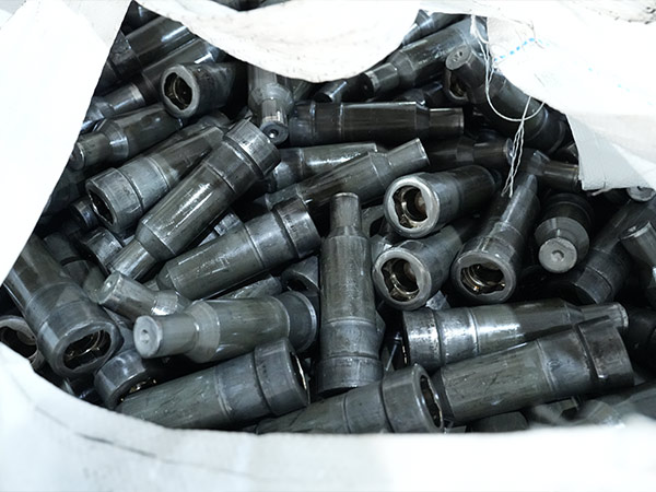
Table of Contents
Key takeaways:
- Cold heading die design affects not only tooling life but also diameter, concentricity, head shape, cavity depth, surface quality, and long-term dimensional consistency.
- Premature die failure is rarely caused by one factor. Tool geometry, stress concentration, material selection, heat treatment, lubrication, alignment, blank consistency, and maintenance work together.
- Fatigue cracking, abrasive wear, adhesive wear, edge chipping, plastic deformation, and surface pickup are different failure modes and require different corrective actions.
- A harder tool material is not automatically a better choice. Tooling must balance wear resistance, compressive strength, fracture toughness, and resistance to cyclic loading.
- Sharp transitions and insufficient support can create local tensile stresses even when the main forming load is compressive.
- Prestressed die assemblies can reduce damaging tensile stresses in heavily loaded inserts when interference, case geometry, and assembly are correctly designed.
- Punch-to-die alignment is essential for concentricity, equal wall thickness, balanced loading, and reliable punch life.
- Lubrication controls friction, forming load, surface pickup, temperature, material flow, and tooling wear.
- Blank length, wire diameter, hardness, surface condition, and material chemistry must remain stable because every variation changes the load applied to the tooling.
- Tool maintenance should be based on dimensions, surface condition, load history, and defect trends rather than waiting for complete breakage.
- Buyers should evaluate whether a supplier designs, manufactures, measures, repairs, and stores tooling in-house.
- Tool life should be managed as a controlled production metric rather than treated as a fixed number that applies to every cold-headed part.
Introduction
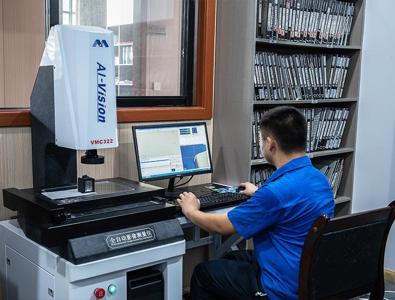
A cold heading die may produce hundreds of thousands of acceptable parts and then begin to create dimensional drift, surface marks, eccentric features, or incomplete filling. In other cases, a punch or die insert may fail suddenly after a much shorter production run.
The difference is not explained by tool material alone.
Cold heading die design is a system-level engineering task. It connects the component drawing, forming sequence, blank geometry, machine alignment, die structure, punch strength, material flow, lubrication, heat treatment, surface finish, maintenance, and inspection strategy.
A die must be strong enough to withstand repeated forming pressure, but strength is only one requirement. It must also maintain its geometry elastically under load, release the component reliably, resist abrasive and adhesive wear, transfer force through a supported structure, and remain measurable and repairable during long-term production.
Research on cold-forging tools shows that repeated loading can bring the die material to its fatigue limit, while variables such as die alignment, material-size deviation, and operating temperature can cause actual factory conditions to differ from ideal simulation results. Real-time forming-load monitoring is therefore increasingly used to improve die-life management. The Scientific Reports study on cold-forging die life-cycle management provides a detailed example.
This guide explains how cold heading die design affects tool life and finished-part accuracy. It is written for product engineers, tooling engineers, quality managers, and procurement teams evaluating custom cold-headed components.
What Is Cold Heading Die Design?
Cold heading die design is the engineering process used to define the tooling system that converts a cut wire blank into the required component geometry.
The design normally covers more than the final cavity. It may include punches, die inserts, cases, sleeves, knock-out pins, cutting tools, transfer fingers, support elements, spacers, guide components, and measuring fixtures.
The Tooling System
The word “die” is often used to describe the complete tool, but an industrial cold heading tool usually contains several interacting components.
Die insert
The die insert contains the working cavity that supports or shapes the outside of the component. It is exposed to high contact pressure, friction, cyclic loading, and localized wear.
The insert may be installed inside a supporting case to improve its resistance to expansion and tensile stress.
Die case
The case surrounds and supports the insert. Its dimensions, material, interference fit, and wall thickness affect how the forming load is distributed.
A correctly designed case can place the insert under beneficial compressive prestress before the production load is applied.
Punch
The punch enters the die cavity and applies force to the blank. It may create a head, recess, hole, slot, extrusion, internal profile, or other feature.
Punches with long slender sections, sharp corners, narrow tips, or insufficient support are more vulnerable to bending, chipping, and fatigue failure.
Knock-out and ejector components
The knock-out system removes the formed component from the die and may also control a local dimension.
Poor ejection design can scratch the component, bend a long part, damage a thin wall, or create repeated shock loading on the tooling.
Cutting and transfer tools
The cut-off knife controls blank length and volume. Transfer fingers move the partially formed component between stations.
Errors in these components can appear as die problems even when the main cavity is correctly manufactured.
Cold Heading Die Design as a Process Chain
A good cavity cannot compensate for an unsuitable forming sequence. Cold heading tooling design must therefore begin with the complete process rather than with the final drawing alone.
Starting blank
The blank defines the amount of material available for every shaft, flange, head, wall, recess, and cavity.
A small blank-volume error can cause short filling, flash, length variation, inconsistent head height, or excessive tool load.
Preform stages
Intermediate shapes distribute deformation across several stations. Their geometry determines where the material moves during the next operation.
A preform may look unrelated to the final component, but it can be essential for preventing folding, cracking, punch overload, and uneven filling.
Final sizing
The last operation may establish critical outside dimensions, flats, splines, recesses, or head geometry.
Final sizing should correct controlled variation rather than compensate for an unstable process created in earlier stations.
Why Tool Life and Part Accuracy Are Closely Connected
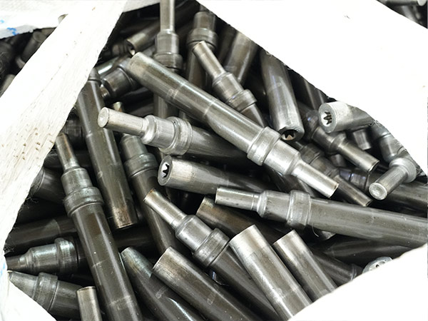
Tool life and part accuracy are not separate production topics. A tool begins influencing dimensional consistency before it reaches complete failure.
Elastic Tool Deflection
A die or punch changes shape slightly under forming load. This elastic movement normally disappears after unloading, but it affects the dimensions created during the operation.
Loaded vs unloaded geometry
The tooling cavity is inspected without production load, while the component is formed when the tooling is under load.
Cold heading die design must account for how inserts, cases, punches, spacers, and machine components behave during the forming stroke.
Unequal support
When one side of the tool receives more support than the other, deformation may become asymmetric.
This can lead to eccentric heads, unequal wall thickness, tapered holes, off-center recesses, or inconsistent flat dimensions.
Progressive Wear
Wear changes the shape of the working surface gradually.
Diameter growth
An outside-forming cavity may become larger as its surface wears. The resulting part diameter can drift toward or beyond its upper specification limit.
Corner loss
Corners and small radii may wear faster than broad surfaces. The component may continue to meet its main diameter while losing profile accuracy or functional engagement.
Surface deterioration
A polished cavity can become scratched or rough. These changes can transfer directly to the part surface and increase ejection resistance.
Fatigue Crack Development
Repeated loading can initiate small cracks at areas of high stress concentration.
Research into cold-forging tool fatigue has examined the influence of notch radius, prestressing method, and tool material on crack initiation and growth. The DTU research summary on fatigue in cold-forging dies describes a method combining low-cycle fatigue testing, crack-growth analysis, and finite element modelling.
Crack before breakage
A small crack does not always cause immediate failure. It may grow across many cycles before the insert breaks.
During this period, the crack can create local surface marks, dimensional variation, or material fins on the finished component.
Sudden failure risk
A crack can also progress rapidly once it reaches a critical size. Waiting for visible tool breakage can therefore create machine damage, mixed batches, and production downtime.
Plastic Tool Deformation
If local tool stress exceeds the material’s usable strength, the working surface may deform permanently.
Cavity collapse
A cavity wall may expand, sink, or change profile. This permanently changes the finished-part dimensions.
Punch tip deformation
A punch tip may flatten or mushroom under repeated load. Hole depth, recess shape, or internal dimensions can then change gradually.
Main Components in Cold Heading Die Design
| Tooling component | Main function | Typical design concerns | Possible effect on the part |
|---|---|---|---|
| Die insert | Forms and supports the outside geometry | Cavity profile, radius, wall thickness, fatigue stress, wear | Diameter, head shape, surface finish |
| Die case | Supports and prestresses the insert | Interference, material, outside diameter, concentricity | Tool life, cavity stability, dimensional repeatability |
| Heading punch | Applies force and forms the head or recess | Tip strength, unsupported length, transition radius | Head height, recess shape, cracks, eccentricity |
| Extrusion punch | Creates holes or internal cavities | Slenderness, alignment, surface finish, support | Hole diameter, depth, wall thickness |
| Knock-out pin | Ejects the part and may form a local feature | Strength, timing, flatness, wear | Overall length, end shape, bending |
| Cut-off knife | Cuts the wire into a controlled blank | Edge condition, timing, clearance, alignment | Blank volume, cut-face quality |
| Transfer finger | Moves the part between stations | Grip position, timing, repeatability | Orientation, surface marks, off-center forming |
| Spacer and support | Establishes tool position and load path | Flatness, parallelism, stiffness | Station alignment and dimension stability |
| Tooling gauge | Verifies wear and setup condition | Datum choice, repeatability, calibration | Maintenance timing and defect prevention |
Eight Factors That Control Cold Heading Die Life
The service life of a cold heading die cannot be predicted from the tooling material alone. The following factors should be reviewed as one connected system.
1. Die Structure and Load Distribution
The first objective of cold heading die design is to transfer forming force through a stable and supported structure.
Insert and Case Design
A die insert is often surrounded by one or more cases or rings. The case provides radial support and can reduce harmful expansion of the insert.
Prestressed tooling
An interference fit can place the insert under compressive stress before production begins. When the forming load is applied, this initial compression can reduce the net tensile stress experienced by the insert.
Research on cold-forging die fatigue indicates that die structure, prestressing, material selection, fabrication, and service conditions all influence tool life. CAE can be used during the design stage to evaluate dynamic tool stress and strain. The Springer study on die fatigue-life design discusses this integrated approach.
Excessive interference
More interference is not automatically better. Excessive prestress may make assembly difficult, damage the insert, distort the cavity, or create high stress elsewhere.
The correct fit depends on insert geometry, case geometry, material properties, working pressure, surface condition, and assembly method.
Working-Wall Thickness
A die wall must be thick enough to resist expansion and fatigue.
Thin local sections
A thin wall near a large cavity, cross hole, relief, or sharp transition can become the weakest point in the load path.
Increasing only the overall outside diameter may not solve the problem if the local geometry still creates concentrated stress.
Corner and Transition Geometry
Sharp tooling transitions behave like notches.
Notch effect
A sharp internal corner can raise local stress and encourage fatigue-crack initiation. A practical radius distributes the load over a larger area.
The radius must still be compatible with the required part geometry and material flow.
Relief placement
A relief can reduce contact and support ejection, but an incorrectly positioned relief may leave a working edge unsupported.
Every relief should have a clear function rather than being added only to simplify machining.
2. Tool Material and Property Balance
Tool materials for cold heading must resist several types of damage at the same time.
Wear Resistance
Wear resistance helps the working surface maintain its profile during repeated contact with the blank.
Abrasive wear
Scale, hard inclusions, wire-surface defects, and hard workpiece materials can remove microscopic particles from the tooling surface.
Abrasive wear often appears as gradual dimensional drift or loss of corner definition.
Adhesive wear
High contact pressure and inadequate lubrication can cause workpiece material to adhere to the tool surface.
The transferred material may then scratch later parts, increase friction, and accelerate further pickup.
Compressive Strength
The tool must withstand high local pressure without permanent deformation.
Local overload
A narrow punch tip, unsupported cavity edge, excessive blank volume, or misaligned tool can create local loads much higher than the average forming pressure.
Material selection should therefore consider the most heavily loaded feature, not only the general component size.
Fracture Toughness
A very hard material may resist wear but remain vulnerable to chipping or cracking.
Hardness-toughness trade-off
Increasing hardness can improve wear resistance but may reduce the ability to tolerate impact, misalignment, and local tensile stress.
Cold heading tool design should select properties according to the dominant failure mechanism.
Material Combination
Different tooling components may require different property balances.
| Tooling position | Required property emphasis | General design logic |
| Wear-intensive cavity insert | Wear and compressive resistance | Maintain dimensions under repeated contact |
| Heavily loaded punch | Compressive strength and toughness | Resist tip deformation and breakage |
| Supporting case | Strength, toughness, dimensional stability | Maintain prestress and support the insert |
| Slender pin | Toughness, fatigue strength, straightness | Resist bending and cyclic failure |
| Cutting tool | Edge retention and impact resistance | Maintain consistent blank length and cut surface |
| Knock-out component | Toughness and wear resistance | Withstand repeated ejection loads |
The final material and heat-treatment choice should be made by the tooling engineer according to geometry, workpiece material, machine speed, lubrication, and expected maintenance strategy.
3. Product Geometry and Forming Sequence
Tool life is strongly influenced by the geometry the tooling is being asked to produce.
Severe One-Stage Deformation
Trying to form a large head, deep cavity, or major diameter reduction in one station can create high peak loads.
Load concentration
When too much material must move at once, pressure rises sharply in restricted regions of the die and punch.
This can accelerate fatigue, cause punch bending, and produce incomplete or unstable material flow.
Progressive Preforming
Multi-station forming divides deformation into controlled stages.
Load sharing
Each station performs a manageable change, reducing the peak load placed on the final tooling.
Material positioning
A preform moves material closer to where it will be needed in the following stage. This reduces the work required to fill difficult corners, flanges, or recesses.
Romy Metal’s Cold Heading Process Guide provides a broader explanation of multi-stage forming, die and punch systems, tool wear, and process monitoring.
Part Radius and Tool Radius
The component’s specified radius directly affects the required tool edge.
Zero-radius expectations
A mathematically sharp part corner may require a fragile tool edge that is unsuitable for repeated production.
Using the largest functionally acceptable radius can improve material flow and cold heading die life.
Hollow and Thin-Wall Parts
Sleeves, bushings, and hollow shafts place special demands on punches and die support.
Punch slenderness
A deep narrow cavity requires a long punch. Its length-to-diameter relationship affects bending and fatigue risk.
Unequal wall thickness
If the punch and die are not concentric, one wall becomes thinner while the opposite wall becomes thicker.
The resulting part may fail dimensional inspection even before the tool visibly wears.
4. Punch and Die Alignment
Alignment is one of the most important factors affecting both tooling life and part accuracy.
Centerline Alignment
The punch should enter the die along the intended centerline.
Side loading
When the punch enters at an angle or offset, one side receives greater load.
This can cause:
- Unequal tool wear
- Punch bending
- Edge chipping
- Eccentric cavities
- Uneven wall thickness
- Off-center heads
- Surface scoring
Station-to-Station Alignment
In multi-station production, the partially formed blank must enter each following die in the correct orientation and position.
Transfer error
A transfer finger that rotates, tilts, or offsets the part can create localized impact during the next operation.
The resulting defect may appear intermittently, making it difficult to diagnose from final inspection alone.
Tool Stack Flatness
Spacers, backing plates, holders, and machine seats should provide flat and parallel support.
Angular error
A small angular error across the tooling stack can become significant at the end of a long punch.
This is why alignment should be evaluated through the complete machine-tool assembly rather than by measuring the insert alone.
Concentricity Control
Cold heading die design should define a consistent datum system for the insert, case, punch, holder, and inspection fixture.
Measurement consistency
If tooling components are measured from different references, they may each pass inspection while the assembled system remains misaligned.
A clear datum chain improves both tool manufacturing and production setup.
5. Lubrication and Friction Control
Lubrication is part of the forming system, not merely a production consumable.
Friction and Forming Load
Higher friction restricts material movement along the tool surface.
Increased pressure
When material cannot flow as intended, the machine must apply more force to fill the same cavity.
The additional load is transferred directly to punches, inserts, cases, and machine components.
Adhesive Pickup
Some workpiece materials are more likely to adhere to tooling surfaces.
Progressive damage
A small pickup point increases local roughness. The rough surface then removes more lubricant and attracts additional material.
This cycle can quickly produce surface scratches and high ejection force.
Lubricant Distribution
Having lubricant present does not guarantee that it reaches every high-pressure interface.
Deep cavities
Lubricant may be displaced from deep or narrow contact regions during extrusion.
The tooling design, wire treatment, lubricant type, application method, and forming sequence must work together.
Contamination
Dirty lubricant or foreign particles can damage polished working surfaces.
Abrasive particles
Metal fragments, scale, dust, or degraded coating material can become trapped between the part and tool.
This can cause random scratches that gradually develop into stable wear tracks.
Lubrication Diagnosis
Signs that lubrication should be investigated include:
- Increasing forming load
- Rising tool temperature
- Surface pickup
- Scoring
- Difficult ejection
- Shortened punch life
- Unstable part finish
- Increased dimensional variation
Lubrication should be reviewed together with surface preparation and tool finish rather than adjusted in isolation.
6. Raw-Material and Blank Consistency
The die experiences the consequences of every variation in the incoming material.
Wire Diameter
A larger wire diameter increases the volume and contact conditions of the blank.
Overfill
Excess material may create higher pressure, flash, folding, excessive component length, or tool overload.
Underfill
Insufficient material may leave the head, flange, or cavity incomplete.
Cut Length
Blank length combines with wire diameter to determine volume.
Cut-off variation
A worn knife, unstable feeding system, or incorrect timing can create inconsistent blanks.
The resulting part variation may be mistaken for cavity wear.
Material Hardness
Harder material generally requires higher forming force.
Lot-to-lot changes
Even when the nominal material grade remains the same, variation in annealing, drawing condition, microstructure, or hardness can affect the production load.
The supplier should define incoming-material controls appropriate to the severity of the forming process.
Surface Condition
Wire scratches, seams, scale, and coating irregularities affect both the part and tooling.
Local stress
A material defect can open during deformation and produce a crack on the part.
Tool contact
A rough or contaminated wire surface can accelerate abrasive wear and damage polished cavities.
Chemistry and Work-Hardening Behavior
Materials with different alloy content and strain-hardening behavior do not flow identically.
Process-specific tooling
A tool developed for one material condition may experience significantly different loads if the material is changed without a new engineering review.
Material substitutions should therefore be controlled through an approved change process.
7. Tool Manufacturing and Surface Integrity
Cold heading die design can be technically correct but still fail because of how the tool is manufactured.
Machining Accuracy
Insert, case, and punch dimensions affect assembly alignment and prestress.
Roundness and cylindricity
An insert that is not round may receive uneven support from the case.
Taper
An unintended taper can create localized contact during assembly or allow movement under load.
Grinding and Polishing
Working surfaces influence friction, material flow, and surface finish.
Directional marks
Grinding marks positioned across the material-flow direction can increase friction or initiate pickup.
Over-polishing
Excessive polishing can alter a critical radius or edge profile.
The surface should be improved without changing the designed geometry.
EDM Surface Condition
Electrical discharge machining can create detailed cavities, but the resulting surface may require additional finishing.
Recast layer
A damaged or brittle surface layer can become a crack-initiation location under cyclic loading.
The required finishing process depends on tool material, cavity function, stress level, and desired surface quality.
Heat-Treatment Distortion
Tool heat treatment can affect size, straightness, roundness, and residual stress.
Finish-machining allowance
Tooling should be manufactured with a route that allows critical dimensions to be finished after the processes most likely to change them.
Assembly Damage
An insert can be damaged while being pressed into its case.
Incorrect assembly method
Poor surface preparation, incorrect interference, misalignment, excessive force, or local impact may create hidden cracks before production begins.
Assembly procedures should be documented and repeatable.
8. Temperature, Production Speed, and Maintenance
Cold heading is performed without heating the blank to conventional forging temperatures, but the tooling still generates heat through deformation and friction.
Thermal Accumulation
Continuous production can raise the temperature of tools, lubricant, and machine components.
Dimensional influence
Thermal expansion can change the relationship between punches, inserts, cases, and holders.
Lubricant influence
Lubricant behavior may change as temperature rises, affecting film strength and friction.
Production Speed
Increasing cycle rate can raise output, but it also reduces the time available for cooling, lubrication, ejection, and defect detection.
Stable speed vs maximum speed
The best production speed is not necessarily the highest possible machine speed.
A stable operating window should balance output, tool temperature, part quality, machine load, and tooling life.
Preventive Maintenance
Maintenance should occur before tool failure creates mixed production or machine damage.
Condition-based control
Useful maintenance indicators include:
- Cumulative part count
- Forming-load trend
- Dimensional trend
- Surface-defect trend
- Ejection force
- Visual crack inspection
- Tool-temperature trend
- Punch and die alignment
- Tooling repair history
The Scientific Reports die-life management study demonstrates how real-time forging-load data can support more practical die replacement decisions than relying only on operator experience.
Common Cold Heading Die Failure Modes
| Failure mode | Typical appearance | Possible causes | Effect on production | Corrective direction |
| Fatigue cracking | Fine crack growing from a radius or notch | Cyclic tensile stress, insufficient support, sharp transition | Fins, marks, sudden insert fracture | Modify radius, prestress, load path, material, process sequence |
| Abrasive wear | Gradual surface or profile loss | Hard material, scale, inclusions, rough wire | Oversized features, lost corner detail | Improve material surface, tool material, coating, lubrication |
| Adhesive wear | Workpiece material attached to tool | Poor lubrication, rough surface, material compatibility | Scratches, pickup, high ejection force | Improve polish, lubricant, surface treatment, process temperature |
| Edge chipping | Small pieces missing from tool edge | Brittle material, sharp edge, impact, misalignment | Local fins, incomplete profile | Increase edge support, radius, toughness, alignment control |
| Plastic deformation | Flattened punch or expanded cavity | Local overload, insufficient compressive strength | Permanent dimensional change | Reduce load, improve support, revise tool material |
| Punch bending | Curved or off-center punch | Excessive slenderness, misalignment, side loading | Eccentric holes, unequal walls | Shorten unsupported length, improve guidance and alignment |
| Surface cracking | Network or localized surface cracks | Poor surface integrity, grinding damage, cyclic stress | Marks transferred to parts | Improve manufacturing and finishing route |
| Case splitting | Crack in supporting case | Excessive interference, poor material, local stress | Loss of prestress, major tool failure | Recalculate fit and case geometry |
| Insert movement | Cavity position changes in case | Insufficient interference, contamination, assembly error | Inconsistent alignment and dimensions | Improve assembly fit and surface control |
| Knock-out failure | Bent, chipped, or broken ejector | High ejection load, poor timing, weak geometry | Part jams, damaged ends, downtime | Improve release angle, timing, lubrication, component strength |
What Makes a Cold Heading Die Fail Early?
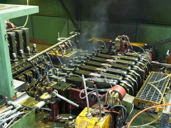
Early failure often occurs when several moderate risks combine.
Stress Concentration Plus Brittle Tooling
A sharp corner may be acceptable under ideal alignment, while a hard brittle tool may survive under perfectly centered loading. When both risks exist together, a small setup error can initiate a crack quickly.
System interaction
Cold heading die design should be reviewed for realistic factory variation rather than only ideal nominal conditions.
High Load Plus Poor Support
A severe forming operation may produce acceptable parts during sampling, but insufficient die support can create fatigue damage during repeated production.
Sample success is not tool-life proof
A short sample run demonstrates basic feasibility. It does not prove that the tooling structure will remain stable across the expected production volume.
Misalignment Plus Slender Punch
A long punch may work when perfectly aligned. A small centerline error can create bending stress during every stroke.
Repeated side loading
Even when the punch does not break immediately, repeated bending can shorten fatigue life and create dimensional drift.
Material Change Plus Unchanged Process
A harder material lot, different wire coating, or alternative alloy can increase load and friction.
Controlled substitution
Material changes should be reviewed by engineering rather than handled only as purchasing substitutions.
Poor Lubrication Plus High Production Speed
Higher production speed can increase tool temperature while reducing lubricant recovery.
Accelerated pickup
Once adhesive wear begins, friction and temperature rise further, creating a self-reinforcing failure cycle.
How Cold Heading Die Design Controls Part Accuracy
Tool accuracy is not simply a matter of machining the cavity to the nominal drawing dimension.
Cavity Geometry
The cavity defines the component’s basic form.
Size Compensation
Tooling engineers may need to account for:
- Elastic tool deflection
- Material springback
- Heat-treatment change
- Coating allowance
- Expected wear direction
- Final sizing operations
A cavity manufactured directly to the finished nominal dimension may not always produce the required part dimension under load.
Radius and Profile Control
Small profile details can affect assembly even when the main diameter remains acceptable.
Functional engagement
Splines, flats, recesses, gear-like features, and polygonal profiles may depend on corner shape and profile depth.
The inspection plan should therefore measure functional geometry rather than only broad outside dimensions.
Punch Position
Punch position controls holes, recesses, cavities, slots, and head features.
Axial Position
Incorrect punch depth may change:
- Hole depth
- Web thickness
- Overall length
- Head height
- Recess depth
- Bottom thickness
Radial Position
An off-center punch can change wall thickness, concentricity, and material flow.
For rotating, sealing, or press-fit components, this error may be more important than the individual diameter tolerances.
Tooling Elasticity
The tooling assembly deforms temporarily under load.
Repeatable Elastic Movement
Repeatable deflection can be compensated for during tool design and setup.
Changing Elastic Movement
If the load changes because of material hardness, blank volume, friction, or temperature, the amount of deflection may also change.
This is one reason why part dimensions can shift even when the cavity has not visibly worn.
Die Wear Direction
Different features wear in different directions.
External-forming cavity
Wear may increase the finished outside dimension.
Internal-forming punch
Wear may reduce the diameter of a formed hole or change the internal profile.
Shoulder and end-face tooling
Wear can affect overall length, flange thickness, and local flatness.
The maintenance plan should define expected wear direction for every critical dimension.
Ejection and Part Release
A part can leave the forming cavity within tolerance and become distorted during ejection.
Long components
A long shaft may bend if ejection force is off-center.
Thin-wall components
A sleeve may expand, collapse, or become oval if it sticks to the punch.
Surface damage
Insufficient release or rough tooling can create drag marks that affect sealing, appearance, or later coating.
Cold Heading Die Design vs Standard Machining Tooling
| Comparison factor | Cold heading die design | CNC machining tooling |
| Main working load | Repeated high compressive and cyclic load | Cutting force distributed through tool edge |
| Geometry creation | Material is forced into or around the tooling | Material is removed along a programmed path |
| Tooling investment | Usually dedicated to the component | Programs and fixtures may support several variants |
| Wear effect | Can change full cavity dimensions and profiles | Often affects local cut size or surface finish |
| Load sensitivity | Strongly affected by blank volume and material flow | Strongly affected by feeds, speeds, tool engagement |
| Alignment importance | Critical for concentric forming and equal walls | Critical for runout, position, and setup accuracy |
| Lubrication role | Controls flow, pressure, pickup, and ejection | Controls heat, cutting wear, chip evacuation |
| Tool failure risk | Fatigue fracture, wear, chipping, deformation | Edge wear, chipping, thermal damage, breakage |
| Repair approach | Repolishing, regrinding, insert replacement, rebuild | Insert replacement, tool regrind, fixture correction |
| Economic strength | Repeat high-volume production | Prototypes, low volume, complex or changing features |
Cold heading and machining are frequently combined. A cold-headed blank can create the main material-efficient shape, while machining finishes holes, journals, grooves, or other critical features.
How Does Die Design Affect Dimensional Consistency?
Dimensional consistency depends on whether the process produces the same load, material flow, tool position, and release behavior during every cycle.
Stable Tool Support
A securely supported insert maintains its position and shape under repeated loading.
Loose or moving components
Microscopic movement can change alignment, accelerate wear, and create fretting damage between tooling components.
Stable Blank Volume
Consistent wire diameter and cut length allow the cavity to fill with similar pressure on every stroke.
Volume-driven dimensions
Head height, flange thickness, overall length, and cavity filling can be particularly sensitive to blank variation.
Stable Friction
Lubrication and tool surface condition influence how easily material reaches different areas of the cavity.
Flow imbalance
A local change in friction can cause one side or feature to fill differently even when blank volume remains constant.
Stable Tool Temperature
A process that changes significantly between startup and continuous production may produce a corresponding dimensional shift.
Startup control
The supplier should define when measurements are taken and how the process is stabilized before production approval.
Stable Maintenance Condition
Production should not continue until every dimension reaches its rejection limit.
Warning limits
Internal maintenance limits can be tighter than customer specification limits, allowing the tool to be repaired before nonconforming parts are produced.
Romy Metal’s Cold Heading Tolerance Guide explains how tooling, material, secondary operations, heat treatment, coating, and inspection affect the final tolerance of cold-headed components.
When Should Cold Heading Tooling Be Repaired?
Repair is appropriate when the tooling can be restored without removing too much material, changing the intended geometry, or reducing structural safety.
Polishing and Surface Restoration
Minor pickup, scoring, or roughness may be corrected through controlled polishing.
Geometry protection
Polishing should not round a critical edge, enlarge a cavity, reduce a punch diameter, or change the designed surface profile.
The tool should be remeasured after restoration.
Regrinding
A punch face, cutting edge, or other accessible surface may be reground.
Dimensional compensation
Regrinding removes material. The remaining length, working depth, support, and machine setup must still meet the tool design.
Insert Replacement
A worn or cracked working insert may be replaced while the supporting case is retained.
Case inspection
The case should be checked for cracking, deformation, loss of fit, and surface damage before a new insert is installed.
Component Replacement
A punch, knock-out pin, cutting knife, or transfer component can often be replaced individually.
Matched-tool review
Replacing one component may change alignment or working clearance. The complete tooling set should be checked after replacement.
When Should a Cold Heading Die Be Replaced?
Replacement is usually safer than repair when the tool’s structure or datum system can no longer be restored reliably.
Fatigue Cracks
A crack in a highly loaded insert or case can continue to grow.
Crack removal limits
Grinding away a crack may reduce the working wall, alter prestress, or move the cavity beyond its intended geometry.
Permanent Deformation
A collapsed cavity, mushroomed punch, or distorted case indicates that the tool has exceeded its usable load capacity.
Shape restoration
Even when the surface can be machined back to size, the underlying material or stress condition may no longer be reliable.
Excessive Dimensional Loss
Repeated polishing and regrinding eventually consume the available repair allowance.
Remaining geometry
A tool should be replaced when another repair would weaken support, reduce working length, or change the intended load path.
Repeated Short-Life Repairs
A repaired tool that repeatedly fails in the same location indicates an unresolved design or process problem.
Root-cause review
The supplier should review:
- Stress concentration
- Prestress
- Tool material
- Heat treatment
- Forming sequence
- Alignment
- Lubrication
- Blank consistency
- Production load
Replacing the same design without addressing the cause may only repeat the failure.
Tool Repair vs Replacement Comparison
| Tool condition | Repair may be appropriate | Replacement is usually safer |
| Light surface pickup | Controlled polishing restores finish | Pickup has created deep scoring or cracks |
| Minor abrasive wear | Regrind remains within dimensional allowance | Profile or cavity size cannot be restored |
| Cutting-edge wear | Edge can be reground and reset | Tool has chipped deeply or lost support |
| Small removable defect | Defect is outside a high-stress zone | Defect is connected to a fatigue crack |
| Insert wear | New insert can be fitted to a sound case | Case is cracked, distorted, or has lost interference |
| Punch length change | Setup can compensate safely | Remaining punch is too short or unsupported |
| Repeated dimensional drift | Wear source is clearly understood | Tool structure is unstable or permanently deformed |
| Crack indication | Only after engineering assessment | Crack lies in a critical working or support region |
Cold Heading Tool Maintenance Checklist
Before Installation
- Confirm tool identification and drawing revision.
- Check insert, case, punch, and support-component dimensions.
- Inspect working surfaces for scratches, chips, cracks, and corrosion.
- Verify the correct material and heat-treatment record where required.
- Check interference and assembly condition.
- Confirm datum surfaces are clean.
- Measure punch and die concentricity.
- Verify spacers and backing surfaces are flat and parallel.
- Confirm lubrication passages and release features are clear.
- Record the tool’s initial condition.
During Machine Setup
- Verify tool orientation.
- Check punch-to-die alignment.
- Confirm transfer timing and position.
- Confirm cut-off length and blank weight.
- Use the approved material lot and lubricant.
- Begin at a controlled setup speed.
- Inspect the first pieces from every station where possible.
- Measure critical dimensions before increasing speed.
- Record initial forming-load values where monitoring is available.
During Production
- Monitor critical part dimensions.
- Watch for increasing forming load.
- Check surface finish and material pickup.
- Inspect head filling and cavity detail.
- Monitor concentricity and wall thickness.
- Check ejection and transfer stability.
- Record tool changes and adjustments.
- Separate parts made before and after major tooling adjustments.
- Maintain material-lot traceability.
- Stop production when warning limits are reached.
After Removal
- Clean the tooling without damaging polished surfaces.
- Inspect for cracks, chips, wear, deformation, and pickup.
- Measure defined wear points.
- Compare dimensions with the new-tool record.
- Record the number of production cycles.
- Identify whether removal was planned or caused by a defect.
- Repair only through an approved process.
- Protect the tool against corrosion.
- Store matched components together.
- Update the tooling-life history.
What Should Buyers Ask About Cold Heading Die Design?
A buyer does not need to design the tooling, but should understand how the supplier controls it.
Is Tooling Designed In-House?
In-house design can improve communication between the product engineer, process engineer, production team, and toolmaker.
Engineering-change speed
When a trial reveals incomplete filling, excessive load, or dimensional variation, an internal tooling team may be able to adjust the preform, punch, insert, or support structure more efficiently.
Is Tooling Manufactured In-House?
Internal manufacturing can improve control over tool revisions, dimensions, confidentiality, and repair scheduling.
Outsourcing is not automatically a problem
A supplier may use qualified specialist partners successfully. The important issue is whether tool specifications, inspection, change control, and delivery are managed reliably.
How Is Tooling Inspected?
Ask which dimensions and surface conditions are checked before assembly and production.
Useful capabilities
Depending on the tool, inspection may include:
- Optical measurement
- Coordinate measurement
- Roundness measurement
- Surface-roughness measurement
- Contour measurement
- Hardness testing
- Crack detection
- Dedicated gauges
How Is Tool Life Recorded?
The supplier should be able to associate tooling condition with production quantity and defect history.
Minimum record
A useful record may include:
- Tool identification
- Part number
- Tool revision
- Installation date
- Removal date
- Number of parts produced
- Removal reason
- Repair action
- Critical measurements
- Failure photograph
- Root-cause conclusion
Are Spare Tools Available?
High-volume production should not depend on one irreplaceable insert or punch.
Risk-based spares
The spare strategy should reflect tool-manufacturing lead time, failure risk, annual volume, delivery commitments, and customer safety-stock expectations.
How Are Tooling Changes Approved?
A tooling change may affect dimensions, material flow, surface condition, or mechanical performance.
Controlled change
The supplier should define when a change requires:
- Internal validation
- New sample inspection
- Capability study
- Customer notification
- PPAP resubmission
- Functional retesting
How Buyers Can Compare Tooling Capability Between Suppliers
| Supplier evaluation item | What to ask for | Why it matters |
| Tool-design responsibility | Internal engineer, external partner, or machine operator | Shows who controls process knowledge |
| Forming simulation | Whether FEM or another method is used for difficult parts | Helps identify flow and stress risks before trial |
| Tool-manufacturing capability | Available grinding, EDM, polishing, and measuring equipment | Affects revision speed and accuracy |
| Prestressed die experience | Examples of insert and case design | Important for highly loaded cavities |
| Tool-life records | Historical cycles and failure reasons | Shows whether tooling is managed systematically |
| Preventive maintenance | Defined limits and inspection frequency | Reduces unexpected breakage |
| Spare-tool strategy | Number and timing of spare inserts and punches | Supports supply continuity |
| Repair procedure | Approved polishing, grinding, and replacement methods | Prevents uncontrolled geometry changes |
| Change control | Documentation and customer notification process | Protects approved production status |
| Tool storage | Identification, corrosion protection, and matched-set control | Prevents setup errors and tool damage |
How Romy Metal Supports Cold Heading Tool Development
Romy Metal states that it operates an in-house mold workshop with high-precision equipment for independent mold research, development, and manufacturing. Its website also describes more than 30 years of mold-development experience and a product-development process covering drawings or samples, precision mold design, trial runs, mass production, inspection, and delivery.
In-House Mold Development
Romy Metal’s About Us page presents precision tooling development as a central part of its custom cold-heading service.
Design communication
Product requirements, forming feasibility, tolerance priorities, and expected volume can be reviewed before mold manufacturing begins.
Trial adjustment
Prototype results can be used to revise preforms, working cavities, punches, clearances, or secondary operations before mass production.
Custom Cold Heading Solutions
The company’s Custom Cold Heading Solutions cover non-standard hollow sleeves and bushings, special-shaped shafts, gears, splines, polygonal parts, long-rod components, and other drawing-based products.
These components place different demands on cold heading die design. A hollow sleeve emphasizes punch alignment and wall-thickness control, while a spline or polygonal shaft places more attention on corner filling, profile wear, and ejection.
Product Applications
Romy Metal’s full product range includes automotive shafts, sleeves, valve-related components, adjustment parts, mounting columns, inserts, gears, and industrial cold-headed parts.
For example, the company’s Valve Stem uses one-step cold heading to create slotted and two-flat functional geometry. Such features require the tooling to control punch position, profile accuracy, corner condition, and part release.
Process and Tolerance Resources
The Cold Heading Process Guide provides additional information about forming stations, punches, dies, wear mechanisms, process monitoring, and quality control.
The Cold Heading Tolerance Guide explains how buyers can define critical dimensions and decide which features should remain formed or receive secondary machining.
Project Information to Submit
For a tooling and manufacturability review, buyers should send:
- Controlled 2D drawing
- 3D model
- Material grade
- Starting material condition
- Heat-treatment requirements
- Surface-treatment requirements
- Critical dimensions
- Annual production volume
- Typical order quantity
- Expected program life
- Current manufacturing problem
- Required quality documents
- Target sample and production dates
Project drawings and requirements can be submitted through the Romy Metal contact page.
Common Cold Heading Tooling Mistakes
Selecting the Hardest Available Material
Maximum hardness does not guarantee maximum tool life.
Better approach
Identify whether the dominant risk is wear, fatigue cracking, chipping, plastic deformation, or adhesive pickup. Select the tool-material properties for that failure mechanism.
Designing Only the Final Cavity
The final die cannot correct every problem created by an unsuitable blank or preform.
Better approach
Design the complete forming sequence and evaluate the load at each station.
Ignoring Tool Deflection
A cavity may pass inspection while producing an incorrect dimension under load.
Better approach
Consider loaded tool behavior, support stiffness, and real forming pressure.
Treating Lubrication as a Purchasing Item
Changing lubricant can change load, material flow, surface finish, ejection, and tool wear.
Better approach
Control lubricant type, concentration, application, contamination, and compatibility with the wire coating.
Continuing Until Tool Breakage
Complete failure is a late maintenance signal.
Better approach
Use dimensional warning limits, load trends, surface-defect trends, and scheduled tool inspections.
Repairing Without Measuring
Uncontrolled polishing may temporarily remove a surface mark while changing the cavity geometry.
Better approach
Measure the tool before and after repair and document the amount of material removed.
Changing Material Without Tooling Review
An alternative material may require higher force or behave differently during deformation.
Better approach
Treat material substitution as an engineering change and review the forming process, lubrication, tool load, and sample results.
Evaluating Only the Initial Sample
A new tool can produce excellent first samples but still have an unsuitable fatigue-life design.
Better approach
Evaluate tooling performance during a production-representative run and track dimensions and load over time.
Conclusion
Cold heading die design controls far more than the shape of the first approved sample. It determines whether the production process can maintain dimensions, surface quality, alignment, and output throughout the expected program life.
The most important influences on cold heading die life are:
- Die structure and load distribution
- Prestress and insert support
- Tool material and heat treatment
- Product geometry
- Forming sequence
- Punch and die alignment
- Lubrication and friction
- Blank volume and material consistency
- Tool-manufacturing quality
- Production speed and temperature
- Preventive maintenance
- Repair and replacement criteria
Fatigue cracks, abrasive wear, adhesive pickup, chipping, and plastic deformation should not be treated as the same problem. Each failure mode has different causes and requires a different corrective action.
The same is true for part accuracy. A dimensional change may come from cavity wear, tool deflection, punch misalignment, blank variation, temperature, lubrication, ejection, or a transfer error. Replacing the die without identifying the real cause may not solve the problem.
For buyers, the most reliable supplier is not simply the company that owns cold heading machines. It is the supplier that can connect component design, forming engineering, mold development, process control, inspection, maintenance, and change management.
A structured cold heading tooling system helps reduce sudden downtime, uncontrolled dimensional drift, repeated sampling, mixed batches, and long-term supply risk.
FAQ
What is cold heading die design?
Cold heading die design is the process of developing punches, die inserts, cases, ejectors, cutting tools, transfer components, and forming stages that convert wire into a finished or near-net-shape component.
It includes cavity geometry, load distribution, tool material, prestress, alignment, surface finish, lubrication, maintenance, and inspection.
What makes a cold heading die fail early?
Common causes include excessive forming load, sharp stress concentrations, insufficient insert support, unsuitable tool material, poor heat treatment, punch misalignment, inadequate lubrication, inconsistent blanks, damaged wire surfaces, excessive speed, and uncontrolled tool repair.
Early failure usually results from several interacting factors rather than one isolated problem.
What is the most common cold heading die failure mode?
Fatigue cracking is a major failure mechanism in highly loaded cold-forging dies, while wear and adhesive pickup are also common.
The dominant failure mode depends on the component geometry, workpiece material, forming pressure, tool structure, lubrication, and production conditions.
How does cold heading die design affect part accuracy?
The die cavity controls external geometry, while punches control holes, recesses, and internal features. Tool deflection, wear, alignment, prestress, and ejection can change the dimensions produced under load.
A correctly manufactured cavity can still produce inaccurate parts if the tooling assembly or production process is unstable.
Why do cold heading punches break?
Punches may break because of excessive load, insufficient support, high slenderness, sharp transitions, misalignment, weak material, poor heat treatment, surface damage, or repeated bending.
A broken punch should be investigated rather than replaced automatically with an identical part.
Does a harder die always last longer?
No. Higher hardness can improve wear resistance, but it may also reduce fracture toughness.
Cold heading die design must balance hardness, compressive strength, toughness, fatigue resistance, and compatibility with the expected failure mechanism.
What is a prestressed cold heading die?
A prestressed die uses an interference-fitted case or ring to place the working insert under compression before the forming load is applied.
This can reduce damaging tensile stress in the insert, but the interference and case design must be calculated carefully.
How does lubrication improve die life?
Lubrication reduces friction, forming pressure, adhesive pickup, heat generation, scratching, and ejection force.
Its effectiveness depends on the wire coating, lubricant type, application method, tool surface, workpiece material, and forming sequence.
How does die alignment affect cold-headed parts?
Poor alignment can create off-center heads, eccentric holes, unequal wall thickness, tapered cavities, punch bending, uneven wear, and edge chipping.
Alignment should be verified across the punch, die insert, case, holder, spacers, and machine setup.
How often should cold heading tooling be inspected?
Inspection frequency depends on part risk, tool history, annual volume, material, forming severity, and expected life.
High-risk tooling may need in-process dimensional monitoring and scheduled visual or crack inspections before the normal replacement count is reached.
How can tooling wear be detected before failure?
Useful indicators include dimensional drift, surface marks, rising forming load, increasing ejection force, material pickup, changing wall thickness, loss of profile detail, and visible cracks.
Tool-life records should connect these indicators with production quantity and material lots.
When can a cold heading die be repaired?
Light pickup, minor wear, accessible cutting-edge wear, and replaceable inserts may be repairable when the original geometry and structural safety can be restored.
Every repair should be controlled, measured, documented, and followed by part verification.
When should a cold heading die be replaced?
Replacement is generally recommended for fatigue cracks in critical areas, permanent deformation, deep chipping, damaged supporting cases, excessive dimensional loss, or repeated short-life repairs.
The root cause should be corrected before making an identical replacement.
Can finite element simulation predict cold heading die life?
Simulation can identify stress concentration, tool deflection, material flow, and high-risk regions. It is useful for comparing designs and improving tool structure.
Actual tool life can still be affected by alignment, material variation, friction, temperature, manufacturing quality, and other factory conditions. Simulation should therefore be combined with production monitoring and historical data.
Why does blank-length variation damage tooling?
A longer or larger blank contains more material. When excessive volume is forced into a closed cavity, forming pressure can increase sharply.
This may cause flash, folding, tool overload, dimensional variation, and premature punch or insert failure.
Can one cold heading die produce different material grades?
Possibly, but a material change can alter flow stress, work hardening, friction, forming load, and tool wear.
The supplier should review and validate every material change before regular production.
How does cold heading die wear change finished dimensions?
Wear in an external-forming cavity may increase a part diameter or reduce corner definition. Wear on a punch may reduce formed-hole size or change a recess profile.
The expected wear direction should be included in the inspection and maintenance plan.
What should buyers ask a cold heading tooling supplier?
Ask about:
- In-house tool design
- Mold manufacturing equipment
- Forming simulation
- Tool-material selection
- Prestressed die experience
- Tool inspection
- Tool-life records
- Preventive maintenance
- Spare tooling
- Repair procedures
- Engineering-change control
- Production traceability
Is an in-house mold workshop important?
An in-house mold workshop can improve communication, confidentiality, revision speed, maintenance response, and control over tooling dimensions.
However, buyers should also evaluate the workshop’s equipment, inspection capability, procedures, engineering experience, and historical tooling performance.
Can better cold heading die design reduce product cost?
Yes. Longer tool life can reduce downtime, replacement-tool cost, setup frequency, sorting, rejection, emergency production, and delivery risk.
A stable tool can also support higher production efficiency and more consistent finished-part dimensions.