
Table of Contents
Key takeaways:
- Reliable cold heading parts begin with controlled material flow rather than simply copying a machined-part drawing.
- Large diameter changes should normally be distributed across several forming stages instead of forced into one severe operation.
- Practical corner radii and gradual transitions help reduce local stress, incomplete filling, folding, and premature tool damage.
- Deep holes, thin walls, narrow recesses, and sharp internal details require special attention to punch strength and metal flow.
- The selected material must provide suitable ductility, surface condition, hardness, and consistency for the planned deformation.
- Critical functional tolerances should be separated from dimensions that can accept normal forming variation.
- Heat treatment, coating, thread rolling, machining, grinding, and inspection should be considered before production tooling is finalized.
- Drawings should clearly identify datums, finished-condition dimensions, critical features, annual demand, and assembly requirements.
- Early DFM cooperation between the product designer and cold heading manufacturer can prevent repeated sampling and expensive tooling revisions.
Introduction
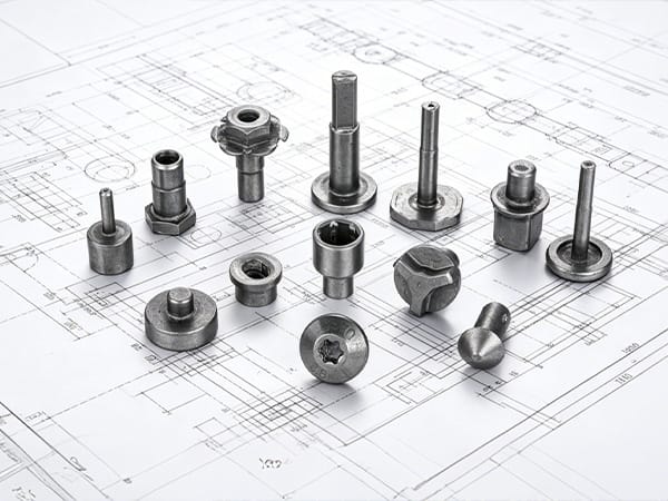
A component may look simple on a CAD drawing but still be difficult to manufacture reliably through cold forming. A large head, deep cavity, thin wall, sharp shoulder, long unsupported shaft, or unnecessarily narrow tolerance can create unstable metal flow and increase the risk of cracks, folds, eccentricity, incomplete filling, and short tool life.
For this reason, successful cold heading parts should be designed around how metal moves under compression. The designer must consider where material begins, where it needs to move, how many forming stations are available, and whether the punches and dies can create and release the required geometry.
Cold heading is part of the broader cold-working family, in which metal is shaped below its recrystallization temperature. Cold working can improve dimensional control and cause work hardening, but it also reduces remaining ductility as deformation increases. This means that a shape that appears geometrically possible may not be practical in one forming stage. (Wikipedia’s overview of cold working)
The purpose of design for manufacturing, or DFM, is not to make every cold heading part visually simple. It is to create geometry that reaches the required function through a stable, repeatable, and economical production sequence.
This guide explains seven practical design rules that can help engineers develop more reliable cold heading parts while reducing trial-tool modifications, secondary machining, production rejection, and long-term supply risk.
Why Design for Manufacturing Matters for Cold Heading Parts
Cold heading parts are created by redistributing a controlled volume of wire or rod. Unlike CNC machining, the process does not simply remove material until the final geometry appears.
ASM International describes bulk metalworking as a group of deformation processes in which tools and dies control material flow. The relationship between the material, tooling, friction, forming force, and process sequence determines whether the required shape can be produced consistently. (ASM Metalworking: Bulk Forming)
Material Flow
Material flow describes how the metal moves when a punch applies pressure. During upsetting, material generally moves outward and the local diameter increases. During extrusion, material is directed forward, backward, or through a restricted opening.
Volume conservation
The blank must contain enough material to fill the intended die cavity. Too little volume can leave corners, flanges, recesses, or heads incomplete, while excessive volume may create flash, folding, tool overload, or uncontrolled length variation.
A stable design allows the manufacturer to calculate blank volume and distribute it predictably across the finished cold heading part.
Progressive Deformation
Complex cold heading parts are commonly formed through multiple stations. Each station performs a controlled change rather than trying to create the full geometry in one impact.
Station-by-station development
A first station may prepare the blank, a second may create a preliminary head, and later stations may form a flange, recess, cavity, spline, hexagon, or other final detail.
Progressive deformation reduces the amount of strain introduced at one location during a single operation. It can also improve tool life and make the final dimensions easier to control.
Tool Access
Every feature must be created by a physical punch, die, insert, cutting tool, or secondary operation. The design should provide enough space for the tool to enter, transmit force, resist deflection, and leave the component after forming.
Punch entry and removal
A cavity that narrows behind its opening may trap the punch or require a collapsible tool that is impractical for high-speed production. Deep narrow holes may also require slender punches that are vulnerable to bending or breakage.
A small geometric adjustment can sometimes transform a difficult feature into one that can be formed directly and repeatedly.
Repeatable Production
Producing one acceptable sample is different from producing hundreds of thousands of stable cold heading parts. Long-run production must account for raw-material variation, lubrication, machine alignment, die wear, heat treatment, coating, and inspection.
Process window
A strong design provides a reasonable manufacturing window rather than working only under perfect conditions. The part should remain conforming when normal, controlled production variation occurs.
This is especially important for automotive, EV, industrial machinery, construction, valve, locking, and other applications that require repeatable assembly performance.
Cold Heading Parts Design Risk Comparison
The following table provides an initial comparison between design features that normally support stable forming and features that require additional engineering review.
| Design area | Lower-risk direction | Higher-risk direction | Possible result |
|---|---|---|---|
| Diameter transition | Gradual change with a practical radius | Abrupt large step with a sharp corner | Cracks, laps, stress concentration |
| Head formation | Volume distributed over several stages | Large head created in one severe upset | Buckling, splitting, incomplete head |
| Hole geometry | Moderate depth and supported wall | Deep narrow hole with a thin surrounding wall | Punch breakage, wall cracking |
| External corner | Rounded transition | Perfectly sharp corner | Poor filling or early die damage |
| Internal corner | Practical punch radius | Zero-radius internal detail | Weak punch edge and incomplete feature |
| Wall thickness | Relatively uniform and supported | Sudden thin section beside a heavy section | Uneven flow and distortion |
| Tolerance strategy | Tight only on functional features | Tight tolerance on every dimension | Extra tooling, machining, and inspection |
| Surface treatment | Final coating condition defined | Coating thickness ignored | Thread or fit interference |
| Secondary operation | Planned before tooling | Added after sample approval | Redesign, extra fixtures, delayed launch |
| Material condition | Grade and hardness selected for forming | Material selected only by final strength | Cracks, excessive forming force |
This table is a screening tool rather than a universal acceptance standard. The final feasibility of cold heading parts depends on material, size, machine capacity, number of stations, production quantity, tolerances, and the supplier’s tooling experience.
Rule 1: Keep the Upsetting Demand Within a Practical Range
Upsetting shortens one section of the blank and increases its diameter. It is the basic operation used to create bolt heads, flanges, collars, ball ends, shoulders, and other enlarged features.
The more material that must move outward, the greater the deformation demand. Trying to create a very large head from a long, narrow unsupported wire section can cause buckling before the material fills the die.
Avoid Severe One-Stage Upsetting
A common design mistake is assuming that any head can be produced from the selected shaft diameter in one operation.
Why the blank may buckle
A long unsupported section behaves like a slender column under compressive loading. Instead of expanding symmetrically, it may bend sideways, producing an eccentric or folded head.
The manufacturer may need to shorten the unsupported length, change the starting wire diameter, add a preliminary forming station, or redesign the head geometry.
Divide Large Diameter Changes Across Several Stations
Multi-station forming allows cold heading parts to reach complex shapes gradually. Each stage can prepare the metal for the following operation.
Preform geometry
A conical, rounded, or partially upset preform can distribute material closer to the final cavity before detailed features are created.
The preform may not resemble the finished component, but it can be essential for controlling material flow and preventing excessive local strain.
Review the Head-to-Shank Relationship
A large flange on a small shaft is often a strong cold-heading application because it can reduce material waste compared with machining. However, the volume change still needs a realistic forming sequence.
Design question
Instead of asking, “Can this head be cold headed?” ask:
“How many stages, what starting wire diameter, and what preform shape are required to produce the head without buckling or cracking?”
The answer depends on material ductility, blank length, diameter ratio, tooling, lubrication, and equipment capacity. A universal ratio should not be applied without a part-specific engineering review.
Better and Riskier Upset Designs
| Design condition | Better approach | Riskier approach |
| Large circular flange | Use two or more progressive upset stages | Form the full flange in one blow |
| Ball-shaped end | Build a rounded preform before final sizing | Force a long straight blank directly into the final ball cavity |
| Wide head with small shaft | Review a larger starting wire or staged reduction | Use very small wire solely to match the final shaft |
| Long headed component | Support and guide the blank during forming | Leave a long slender section unsupported |
| Asymmetric head | Prepare material distribution before final forming | Expect equal material flow into unequal cavity volumes |
Rule 2: Use Practical Radii and Smooth Transitions
Sharp transitions create high local stresses in both the component and the tooling. They also make it difficult for material to fill corners completely.
For more reliable cold heading parts, designers should use practical radii wherever a shaft meets a head, flange, collar, shoulder, cavity, or other major section change.
External Corner Radii
An external radius allows material to flow around the transition more smoothly. It can reduce the likelihood of folding, surface tearing, and concentrated deformation.
Functional clearance
The largest possible radius is not always acceptable because the mating assembly may require clearance. The design should use the largest radius that still permits installation and function.
A washer, bearing, housing, or adjacent shoulder may need a chamfer or relief to accommodate the formed radius.
Internal Corner Radii
An internal corner is normally created by an external edge on a punch. A perfectly sharp internal corner would require a perfectly sharp tool edge, which is weak and difficult to maintain.
Tool strength
A small punch radius increases tool support and reduces edge chipping. It can also improve die filling by allowing material to move into the corner without an abrupt change in direction.
When a sharp internal corner is functionally necessary, secondary machining, broaching, or another finishing operation may be more reliable than forcing the complete feature during cold heading.
Gradual Diameter Transitions
A tapered or radiused transition generally guides metal more effectively than an abrupt step.
Material redirection
When the cross-section changes suddenly, material near the corner may be forced to move differently from material in the center. This can create a fold, lap, local crack, or incomplete corner.
A smoother transition gives the metal a clearer path while reducing peak tooling pressure.
Radiused vs Sharp Feature Comparison
| Feature | Radiused design | Sharp design |
| Head-to-shank transition | Better material flow and lower local stress | Higher crack and tool-chipping risk |
| Flange underside | Easier filling and stronger punch edge | Difficult corner filling |
| Internal recess | Improved punch support | Fragile punch tip |
| Stepped shaft | Gradual load transfer | Stress concentration at the step |
| Hexagon or flat transition | Controlled corner geometry | Risk of incomplete filling or folds |
The radius should be specified on the drawing instead of left undefined. Otherwise, the customer and supplier may use different assumptions during design review and inspection.
Rule 3: Design Holes, Cavities, and Walls Around Punch Strength
Cold heading parts can contain holes, recesses, sockets, internal cavities, and hollow sections. However, these features are often limited by punch strength, wall support, depth-to-opening relationship, and material flow.
A feature that is easy to drill may not be easy to form.
Control Hole Depth
As a hole becomes deeper, the punch becomes longer and more slender. A slender punch is more likely to bend, deflect, wear, or break under repeated loading.
Blind-hole risk
Blind holes are particularly challenging because displaced material must flow around the punch while the cavity fills. Excessive depth can increase pressure at the punch tip and create unstable wall thickness.
A shorter formed pilot hole followed by drilling or reaming may offer a safer manufacturing route.
Maintain Adequate Wall Thickness
The material surrounding a cavity must be thick enough to withstand forming pressure and later service loads.
Thin-wall distortion
A thin wall beside a heavy flange or solid section may stretch unevenly, crack, become eccentric, or collapse during ejection.
The wall also needs enough thickness to remain stable during heat treatment, machining, coating, assembly, and service.
Avoid Abrupt Wall Changes
A thick section feeding directly into a very thin section can produce unequal flow.
Flow imbalance
The material naturally moves toward areas of lower resistance. Without a controlled preform, one area may fill early while another remains incomplete.
Gradual transitions and relatively balanced wall sections can make hollow cold heading parts more predictable.
Review Hole Bottom Geometry
Flat-bottomed, conical, rounded, and stepped holes place different demands on the punch.
Punch tip support
A small-radius or pointed punch tip may experience concentrated stress. A rounded or otherwise supported bottom shape can improve tool strength when the application allows it.
The final hole may also be created through a combination of backward extrusion, piercing, drilling, reaming, or machining.
Formed Hole vs Machined Hole
| Requirement | Formed hole may be suitable | Machined hole may be preferable |
| Moderate axial cavity | Yes | Not always necessary |
| High-volume pilot hole | Yes | Finish only when required |
| Very deep narrow bore | Limited | Usually stronger option |
| Side hole | Rarely direct cold heading | Drilling is normally required |
| Intersecting passage | Difficult | CNC machining is normally preferred |
| Very precise diameter | Possible with sizing in some cases | Reaming, boring, or grinding may be needed |
| Sharp internal step | Tooling-dependent | Machining may be more practical |
Rule 4: Balance Material Volume and Avoid Unstable Thin Sections
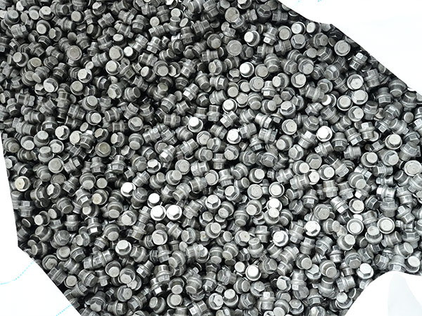
Cold heading parts are produced from a controlled blank volume. Each head, flange, shaft, cavity, recess, and shoulder must receive the correct share of that volume.
A well-designed part does not only fit inside a die. It also gives the material a logical route from the starting blank to the finished geometry.
Start With Volume Distribution
Before tooling is developed, the manufacturer estimates how much material is needed in each section.
Head volume
A large head requires material to move from the original shaft area into the head cavity. If the blank is too short, the head will not fill. If it is too long, excessive material can create folding, flash, or length variation.
Hollow volume
For a hollow cold heading part, material displaced by the punch must move into the wall, flange, bottom, or adjacent section.
The cavity cannot be evaluated separately from the outside shape.
Avoid Isolated Thin Ribs
Thin ribs, lips, webs, and edges may be difficult to fill completely and may be damaged during ejection or handling.
Fragile feature
Even when a thin feature can be produced during initial sampling, it may wear the die quickly or vary as tooling condition changes.
A slightly thicker feature, larger radius, or shorter projection can substantially improve long-run reliability.
Prevent Opposing Material Flows
Some designs require material to move in several directions during the same operation.
Competing flow paths
If one region requires outward upsetting while another requires deep backward extrusion, the material may not divide evenly.
A multi-station process can separate these movements so each stage has a clearer objective.
Consider Starting Wire Diameter Early
Designers sometimes select the final shaft diameter as the starting wire diameter without considering the rest of the part.
Alternative blank strategy
A larger starting wire may reduce the amount of head upsetting but require shaft reduction through forward extrusion. A smaller wire may simplify the shaft but make head formation more severe.
The best starting diameter balances forming severity, material utilization, tooling loads, and available machine capacity.
Rule 5: Select the Material and Wire Condition for Formability
The final component may require high strength, corrosion resistance, wear resistance, conductivity, or low weight. However, the material must also survive the forming sequence.
Cold working generally increases strength and hardness through plastic deformation while reducing remaining ductility. The material grade, prior processing, hardness, microstructure, surface quality, and work-hardening behavior therefore influence how much deformation can be introduced safely.
Ductility
Ductility is the material’s ability to deform plastically before fracture.
Why ductility matters
Cold heading parts with major diameter changes, deep extrusions, or complex recesses require the material to flow without splitting.
A material selected only for high final tensile strength may create excessive forming loads or crack before the final shape is reached.
Hardness
Harder starting material generally requires higher forming force and places greater load on dies and punches.
Controlled starting condition
A material may be supplied in an annealed, spheroidized, drawn, or otherwise prepared condition to support forming. Heat treatment can then be applied after cold heading to achieve the final mechanical properties.
The exact route depends on the alloy, geometry, performance requirement, and customer specification.
Surface Quality
Wire seams, scratches, scale, decarburization, inclusions, or other surface conditions can become more severe as the material is upset or extruded.
Defect propagation
A small longitudinal defect in the wire may open into a visible crack on the enlarged head.
For covered fasteners, ISO 6157-1 establishes limits for various types of surface discontinuities on bolts, screws, and studs. Custom shafts, sleeves, valve parts, and special-shaped components may require customer-specific acceptance criteria rather than automatic application of a standard-fastener requirement.
Lubrication Compatibility
Lubrication affects friction, material flow, surface quality, forming force, and tool wear.
Material-specific behavior
Carbon steel, alloy steel, stainless steel, aluminum, and copper alloys may require different surface preparation and lubricant systems.
A material that forms well under one lubrication system may create galling, pickup, scratches, or unstable flow under another.
Material Selection Comparison
| Material group | General forming consideration | Common design response |
| Low-carbon steel | Usually offers useful ductility | Suitable for many fasteners, sleeves, pins, and general parts |
| Medium-carbon steel | Higher strength but more demanding forming | Review annealing, station count, and post-forming heat treatment |
| Alloy steel | Strong final performance with higher tooling load | Use progressive forming and controlled starting hardness |
| Stainless steel | Strong work hardening and possible galling | Use practical radii, effective lubrication, and robust tooling |
| Aluminum | Lower density and generally lower forming force | Control surface pickup, thin walls, and local deformation |
| Copper alloy | Good conductivity and varied ductility | Confirm exact alloy condition and surface requirements |
Material recommendations should be based on the complete manufacturing route, not only on the final service environment.
Romy Metal’s existing guide comparing steel and aluminum automotive cold heading parts provides a broader comparison of strength, weight, corrosion behavior, tooling, and application requirements.
Rule 6: Apply Tight Tolerances Only Where They Support Function
One of the fastest ways to make cold heading parts unnecessarily expensive is to assign machining-level tolerances to every feature.
The correct tolerance should be based on assembly fit, movement, sealing, torque transfer, alignment, safety, automated feeding, and other functional requirements.
Separate Critical and Non-Critical Dimensions
Not every dimension influences product performance equally.
Critical-to-function features
Common critical features include:
- Press-fit diameters
- Bearing or sealing surfaces
- Thread pitch diameters
- Torque-transmitting flats
- Spline geometry
- Hole position
- Overall assembly length
- Concentric or rotating features
- Safety-related head or flange dimensions
These features may justify tighter tolerances, additional sizing, machining, grinding, dedicated gauges, or statistical process-control requirements.
General formed features
Cosmetic contours, clearance surfaces, non-contact radii, and other non-functional dimensions can usually accept wider manufacturing limits.
Allowing practical variation on these features can simplify tooling and reduce sorting, inspection, and tool replacement.
Distinguish Formed and Finished Dimensions
The drawing should indicate whether a dimension is created directly during cold heading or controlled after another operation.
Formed condition
A directly formed diameter or length may vary with blank volume, tool wear, material condition, and machine adjustment.
Finished condition
A dimension measured after heat treatment, grinding, machining, or coating includes the effects of every previous process.
The acceptance condition must be defined clearly so the customer and manufacturer inspect the same feature at the same stage.
Use Datums and Geometric Controls
A shaft can meet its diameter requirement while still being bent, eccentric, or misaligned.
Datum system
Datums establish the reference surfaces or axes used to measure other features. Without a defined datum system, two inspectors may obtain different results from the same cold heading part.
Geometric requirements such as straightness, perpendicularity, position, profile, and runout should be used when they reflect actual function.
Consider Fits, Not Just Individual Dimensions
The component operates with a mating shaft, hole, nut, bearing, housing, fixture, or assembly tool.
Tolerance stack
A cold heading part may be within its own specification but still fail to assemble when the mating component is near the opposite limit.
The designer should analyze the complete tolerance stack rather than tightening only the cold-headed component.
ISO 286-1 establishes a code system for tolerances on linear sizes and explains basic hole and basic shaft fit principles. Standard fasteners may also reference ISO 4759-1, while custom non-standard parts should use standards only where they are technically applicable.
Romy Metal’s Cold Heading Tolerance Guide explains how formed dimensions, machined features, geometric controls, coating, inspection methods, and process capability affect fit and total cost.
Rule 7: Plan Secondary Operations Before Finalizing the Design
Many cold heading parts require more than one manufacturing process. Possible secondary operations include thread rolling, drilling, turning, milling, broaching, trimming, calibration, grinding, heat treatment, plating, passivation, polishing, cleaning, and final inspection.
These operations should not be added as an afterthought.
Thread Rolling
Threads are often rolled after the blank has been cold headed.
Blank diameter
The pre-roll blank diameter must be controlled because thread rolling displaces material rather than cutting it away. An incorrect blank diameter can affect pitch diameter, crest shape, rolling force, and gauge acceptance.
The drawing should identify the thread standard, pitch, tolerance class, thread length, lead-in, underhead condition, and whether the requirement applies before or after coating.
Heat Treatment
Heat treatment may increase hardness, strength, wear resistance, or fatigue performance.
Dimensional change
Quenching, tempering, carburizing, stress relieving, or other thermal processes can affect straightness, diameter, surface condition, and residual stress.
Critical dimensions should normally be verified after the final heat-treatment stage when heat treatment can alter the feature.
Surface Coating
Zinc plating, zinc-nickel, phosphate, black oxide, passivation, anodizing, and other finishes change the surface condition.
Coating allowance
Coating thickness can reduce thread clearance, increase a shaft diameter, narrow a slot, or change press-fit behavior.
Close-clearance features should be designed and inspected in the agreed finished condition.
Secondary Machining
Machining can finish local features that are inefficient or impractical to form.
Hybrid manufacturing
A near-net cold heading part may be drilled, turned, milled, reamed, or ground only where necessary.
This approach can preserve material efficiency while providing tighter control over holes, bearing seats, sealing surfaces, cross features, or complex internal geometry.
Inspection Planning
The design should state how important features will be verified.
Measurement access
A deep cavity may be easy to specify but difficult to measure. A curved or irregular profile may require a contour measuring system, optical equipment, CMM, fixture, or dedicated gauge.
The measurement method should be agreed before tooling so that the supplier can design appropriate inspection access and references.
Seven Cold Heading Parts Design Rules at a Glance
| Rule | Main design objective | Risk reduced |
| 1. Control upsetting demand | Divide severe diameter changes into practical forming stages | Buckling, head cracks, incomplete filling |
| 2. Use radii and smooth transitions | Guide material and protect tooling edges | Laps, stress concentration, chipped tools |
| 3. Design holes and walls for punch strength | Balance cavity depth, wall thickness, and tool support | Punch breakage, cracked or eccentric walls |
| 4. Balance material volume | Give the metal a predictable path into every feature | Flash, short fill, thin-section distortion |
| 5. Select a formable material condition | Match ductility, hardness, surface, and lubrication to deformation | Cracking, galling, excessive tool load |
| 6. Tolerance by function | Place precision only where it improves assembly performance | Extra machining, inspection, and rejection |
| 7. Plan all downstream operations | Account for threads, heat treatment, coating, machining, and inspection | Late redesign, fixture changes, delayed launch |
How to Redesign Common Cold Heading Part Features
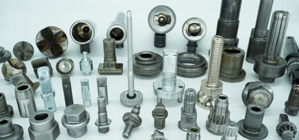
The design rules become easier to apply when they are connected to common component geometries.
Heads and Flanges
A large head can integrate bearing area, anti-rotation geometry, drive features, or assembly stops.
Better design direction
Use practical underside radii, avoid isolated thin edges, and allow the supplier to create one or more preform stages.
Common question
“Can you make the flange larger without changing the shaft?”
Possibly, but the answer depends on available blank volume, starting wire diameter, unsupported length, material ductility, machine capacity, and forming-station availability.
Stepped Shafts
Stepped shafts are common in automotive steering, locking mechanisms, power tools, valves, electrical equipment, and industrial machinery.
Better design direction
Use radiused transitions and distinguish formed shaft sections from surfaces that require grinding or machining.
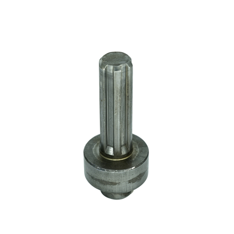
The Automotive Power Steering Gear Shaft shown on the Romy Metal website uses one-step cold heading to create its two-flat cavity, illustrating how a functional internal feature may be integrated when the geometry and tooling route are suitable.
Square, Hexagonal, and Polygonal Features
Flats and polygonal profiles can transmit torque or prevent rotation.
Better design direction
Provide realistic corner radii, adequate feature length, and enough material around the profile. Do not assume that a mathematically sharp corner is required for torque transmission.
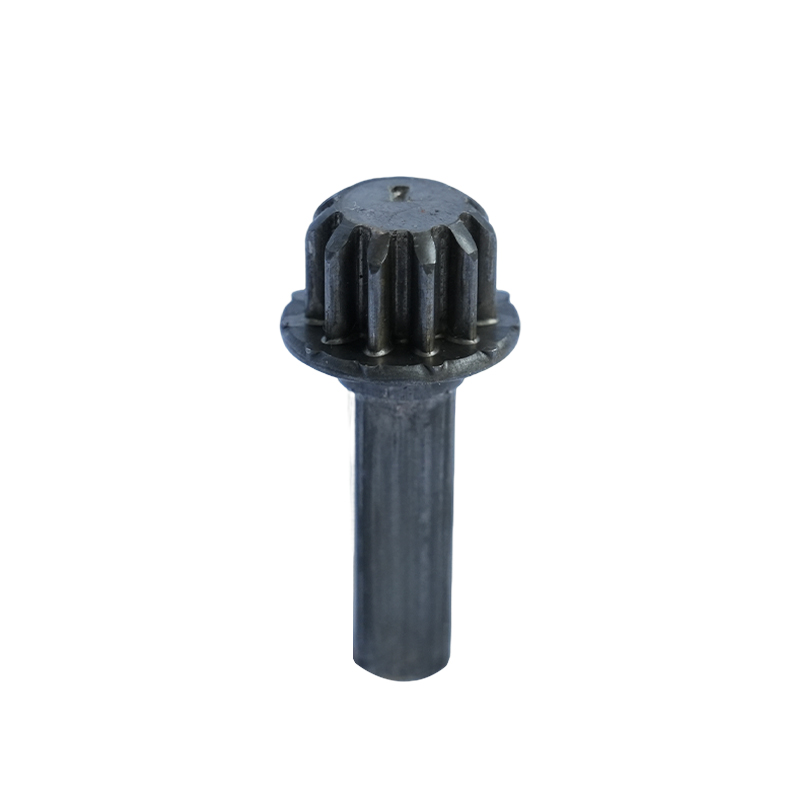
Romy’s Door Lock Square Gear Shaft integrates a square rod and gear structure through cold heading, demonstrating how several external functions can sometimes be combined into one component.
Ball Ends and Rounded Heads
Ball heads may be used in adjustment, steering, measurement, support, or linkage applications.
Better design direction
Build the spherical region progressively and provide a suitable transition between the ball and shaft.
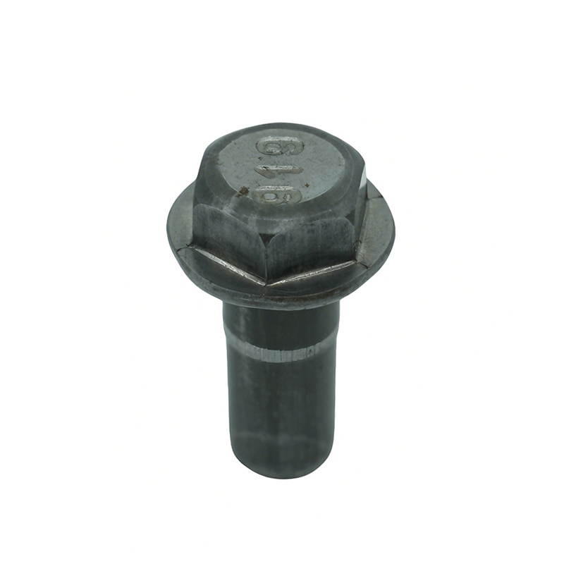
The M12 Ball Head Upper Pressure Rod combines a ball head and hexagonal section formed through one-step cold heading. This type of integration can reduce separate machining or assembly when the part volume and forming sequence are correctly balanced.
Slots and Two-Flat Features
Slots and opposing flats may support torque transmission, adjustment, alignment, or valve operation.
Better design direction
Review punch support, internal corner radii, cavity depth, and material surrounding the feature.
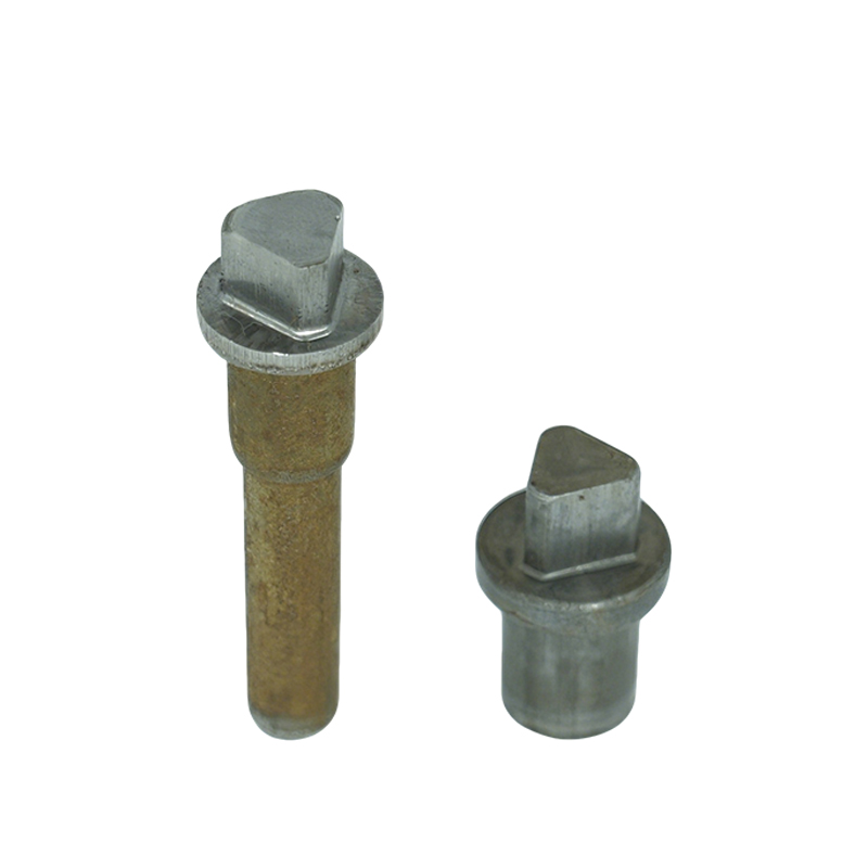
The Valve Stem on the Romy Metal website uses cold heading to form slotted and two-flat dimensions for a water-valve application. It provides a useful reference for designers considering integrated drive or engagement features in cold heading parts.
Sleeves and Bushings
Hollow sleeves may provide spacing, guidance, protection, location, or bearing support.
Better design direction
Control the relationship between cavity depth, outside diameter, wall thickness, bottom thickness, and flange geometry.
A sleeve that combines a deep narrow cavity with a thin wall and wide flange may need several extrusion and calibration stages or a hybrid forming-and-machining route.
Good Design vs Poor Design for Cold Heading Parts
| Application feature | Good DFM approach | Poor DFM approach |
| Headed pin | Rounded head transition and controlled preform | Sharp underside corner and extreme one-stage upset |
| Hollow sleeve | Consistent wall and supported hole bottom | Deep cavity beside an extremely thin wall |
| Torque shaft | Practical flats with defined corner radii | Zero-radius corners copied from a CAD model |
| Flanged component | Material volume balanced between shaft and flange | Starting diameter selected without volume analysis |
| Heat-treated shaft | Finish tolerance specified after heat treatment | Acceptance based only on the as-formed condition |
| Plated thread | Thread class and coating condition defined | Coating added without thread allowance |
| Precision journal | Main body formed and journal finished locally | Machining tolerance required on every formed surface |
| Custom recess | Tool entry, strength, and release considered | Undercut cavity that traps the punch |
| Long component | Blank guided and forming sequence distributed | Long unsupported section compressed directly |
| Automotive part | Critical characteristics and inspection agreed | All dimensions marked equally critical |
Cold Heading Parts DFM Checklist
Before sending a drawing for quotation, review the following questions.
Geometry
- Is the component mainly arranged around a central axis?
- Where must material move outward, forward, or backward?
- Are any diameter changes unusually severe?
- Are sharp corners truly required for function?
- Can practical radii or tapers be added?
- Are any holes too deep for a robust punch?
- Are any walls, ribs, or lips unnecessarily thin?
- Can the part release from the die and punches?
- Are side holes or undercuts expected to require machining?
Material
- Has the exact grade been identified?
- Is the proposed starting hardness suitable for forming?
- Does the material need annealing or other preparation?
- Is the wire surface condition controlled?
- Will the material work-harden significantly?
- Are final properties achieved through forming, heat treatment, or both?
Tolerances
- Which dimensions directly affect assembly or safety?
- Which dimensions can accept wider formed variation?
- Are datums clearly identified?
- Are straightness, runout, profile, or position controls needed?
- Do the requirements apply before or after heat treatment?
- Do the requirements apply before or after coating?
- Has the mating-part tolerance been considered?
- Is the proposed inspection method practical?
Secondary Operations
- Will the part require thread rolling?
- Are holes drilled, pierced, extruded, or reamed?
- Are any diameters machined, ground, or calibrated?
- Is heat treatment required?
- Is plating, passivation, anodizing, or another finish required?
- Does the coating affect a fit or thread?
- Are cleaning and packaging requirements defined?
Commercial Information
- What is the expected annual demand?
- What is the expected lifecycle quantity?
- What is the normal batch quantity?
- Is the design already frozen?
- Are prototypes needed before production tooling?
- Is PPAP, a control plan, traceability, or capability data required?
- Who will own and maintain the tooling?
- What is the target launch schedule?
What Drawings Help a Supplier Assess Cold Heading Feasibility?
A supplier can provide a more accurate DFM review when the drawing explains the component’s function rather than showing only dimensions.
Provide a Controlled 2D Drawing
The drawing should include material, tolerances, datums, surface requirements, heat treatment, coating, thread specifications, and special characteristics.
Drawing revision
Every quotation, sample report, tool design, and production approval should refer to the same revision.
Uncontrolled drawing changes can result in incorrect tooling or inspection disagreements.
Include a 3D Model
A 3D model helps engineers understand the complete geometry and can support tooling and process simulation.
Model limitation
A model does not replace a dimensioned drawing. It usually does not communicate which features are critical, what variation is acceptable, or how the finished part will be inspected.
Explain the Application
Describe how the part is installed and what it must do.
Functional context
Useful information includes:
- Load direction
- Torque requirement
- Mating components
- Press-fit or clearance-fit condition
- Rotation or sliding movement
- Sealing requirement
- Corrosion exposure
- Service temperature
- Vibration or fatigue loading
- Automated assembly method
The supplier may be able to recommend a simpler geometry when the true function is known.
Identify Flexible Features
Mark dimensions or features that may be adjusted during the DFM review.
Controlled redesign
A small change to a radius, hole depth, wall thickness, flange diameter, or tolerance may remove an entire machining operation or forming stage.
Flexible features should still require customer approval before the production drawing is changed.
How Romy Metal Reviews Custom Cold Heading Parts
Romy Metal supplies custom non-standard cold-headed fasteners and precision components developed from customer drawings, samples, and application requirements. Its website lists hollow sleeves and bushings, special-shaped shafts, gears, splines, polygonal bolts, long-rod parts, dimming screws, and other custom cold heading solutions.
Initial Requirement Review
The engineering team reviews the material, geometry, tolerances, annual volume, application, heat treatment, surface treatment, and quality-document requirements.
Process selection
The review determines whether the part should be:
- Completely cold headed
- Cold headed and calibrated
- Cold headed and thread rolled
- Cold headed with secondary CNC machining
- Produced through a different manufacturing process
Not every drawing should automatically be converted into cold heading parts.
Tooling and Forming-Sequence Review
The part is divided into forming stages based on material flow and equipment capability.
Risk identification
The review should identify:
- Severe upset regions
- Thin or unsupported walls
- Weak punch geometry
- Difficult die filling
- Tool-release problems
- Likely crack locations
- Dimensions affected by heat treatment or coating
- Features requiring secondary processing
Sample Validation
Prototype samples allow the buyer to verify dimensions, assembly fit, material, surface quality, and functional performance.
Production-representative conditions
Samples should use the intended material, tooling concept, process route, heat treatment, coating, and inspection method whenever possible.
A machined sample may confirm fit but cannot fully prove the behavior of future cold heading parts.
Mass-Production Control
Stable production requires more than an approved sample.
Long-run control
The production plan should include:
- Raw-material traceability
- Tool inspection and maintenance
- In-process dimensional checks
- Final inspection
- Heat-treatment and coating controls
- Gauge calibration
- Nonconforming-product control
- Engineering-change management
Romy Metal’s custom cold heading solutions and full product range show examples across automotive, EV, industrial, mechanical, elevator, and construction applications.
The broader Cold Heading Process Guide explains the complete route from material selection and wire preparation to tooling, forming, secondary processing, and inspection.
Common Cold Heading Part Design Mistakes
Copying a CNC-Machined Drawing
A drawing developed for machining may contain sharp internal corners, deep bores, narrow grooves, and tight tolerances on every surface.
Better approach
Review the function and redesign the main body for near-net forming. Reserve machining only for features that truly require it.
Choosing Material Only by Final Strength
High-strength material is not always suitable for severe deformation in its final condition.
Better approach
Select a formable starting condition and use work hardening, heat treatment, or surface engineering to reach final performance.
Ignoring Blank Volume
A designer may focus on external dimensions without considering where the metal will come from.
Better approach
Allow the manufacturer to calculate blank volume, starting diameter, preform geometry, and station sequence before tooling approval.
Requiring Perfectly Sharp Corners
CAD systems can create zero-radius geometry that is difficult to reproduce physically.
Better approach
Use practical radii and confirm the maximum allowable radius with the mating assembly.
Adding Coating After the Drawing Is Frozen
A coating can change threads, slots, holes, press fits, and sealing diameters.
Better approach
Define the coating and finished-condition dimensions before tools and gauges are completed.
Approving Only One Sample
One acceptable sample does not prove that a process is stable.
Better approach
Review several samples from a production-representative run and confirm process capability for important characteristics when required.
Conclusion
Reliable cold heading parts are not created by simplifying every shape or applying one universal design formula. They are created by matching the component’s function with controlled material flow, practical tooling, suitable materials, realistic tolerances, and a complete manufacturing route.
The seven most important rules are:
- Keep upsetting demand within a practical range.
- Use radii and smooth transitions.
- Design holes, cavities, and walls around punch strength.
- Balance material volume and avoid unstable thin sections.
- Select the material and wire condition for formability.
- Apply tight tolerances only where they support function.
- Plan secondary operations before finalizing the design.
Early cooperation with the cold heading manufacturer gives engineers more freedom to improve the part before tooling becomes expensive to change. A DFM review can reveal where to adjust a radius, redistribute material, widen a non-critical tolerance, modify a hole, add a forming station, or use local secondary machining.
These decisions can reduce cracking, folding, incomplete filling, punch failure, tool wear, inspection difficulty, repeated sampling, and production delays. More importantly, they help convert a promising CAD design into cold heading parts that remain stable throughout long-term mass production.
Designers and buyers can submit drawings, material requirements, annual demand, application details, and quality-document needs through the Romy Metal contact page for a part-specific manufacturability review.
FAQ
How should a part be redesigned for cold heading?
Start by identifying how material will move from the wire blank into the head, flange, shaft, cavity, or other feature. Add practical radii, reduce abrupt section changes, review hole depth and wall thickness, and separate severe deformation into several forming stages.
The supplier should also review the starting wire diameter, material condition, tooling access, tolerances, and secondary operations before the drawing is finalized.
Which features most often cause cracks in cold heading parts?
Common risk features include sharp head-to-shank transitions, severe one-stage diameter changes, deep recesses, thin walls, surface defects in the wire, and sections that exceed the material’s remaining ductility.
Cracking can also be caused by unsuitable material hardness, poor lubrication, incorrect preform design, or an unstable forming sequence.
Do all cold heading parts need large corner radii?
No. The required radius depends on material, component size, forming load, tool strength, and assembly clearance.
However, a practical radius is normally more reliable than a perfectly sharp transition. The designer should use the largest radius permitted by the component’s function and mating geometry.
Can a deep hole be produced directly by cold heading?
Some axial holes and cavities can be produced through extrusion or piercing. Feasibility depends on hole depth, opening diameter, wall thickness, punch strength, material, and forming sequence.
A deep narrow hole may be created as a shallower formed pilot and finished by drilling, reaming, or boring.
Why do thin walls create problems in cold heading?
Thin walls may not receive material evenly during forming. They can crack, buckle, become eccentric, or distort during ejection, heat treatment, machining, or assembly.
The wall must also be thick enough to support the required service load and inspection method.
What information does a cold heading supplier need from the drawing?
The supplier needs the complete geometry, material grade, tolerances, datums, threads, heat treatment, surface finish, coating, critical characteristics, and finished-condition requirements.
Annual volume, application, mating components, inspection documents, and target schedule are also needed for a useful feasibility review.
Can cold heading parts include square, hexagonal, or spline features?
Yes. Many flats, hexagons, polygonal profiles, splines, gears, recesses, and special head shapes can be integrated through multi-station forming.
The design must provide practical corner geometry, enough material, suitable tool access, and a stable forming sequence.
Should threads be included in the cold heading operation?
The head and blank are commonly cold headed first, while external threads are formed later through thread rolling.
The blank diameter, thread class, coating thickness, thread length, and inspection gauge should be defined before tooling is completed.
Can cold heading parts be machined afterward?
Yes. Cold heading and CNC machining are often combined.
The main body can be formed close to its final shape, while machining finishes deep holes, side holes, bearing seats, sealing surfaces, grooves, or unusually tight local dimensions.
How tight can tolerances be on cold heading parts?
There is no single tolerance that applies to every component. Capability depends on material, part size, geometry, forming sequence, tool condition, machine alignment, heat treatment, coating, and inspection method.
Critical dimensions should be reviewed individually. Some features can be formed directly, while others may require calibration, machining, grinding, or sorting.
Does heat treatment change the dimensions of cold heading parts?
Heat treatment can affect straightness, diameter, hardness, residual stress, surface condition, and overall geometry.
Dimensions that are sensitive to heat treatment should be checked after the final thermal process, and the drawing should state the required inspection condition.
How can designers reduce cold heading tooling cost?
Tooling cost can often be reduced by using practical radii, avoiding unnecessary sharp details, widening non-functional tolerances, simplifying difficult cavities, and reducing the number of secondary features.
Finalizing the drawing before tool production also prevents expensive die, punch, gauge, and fixture revisions.
What is the biggest difference between a good sample and a good production design?
A good sample proves that one or several parts can be manufactured. A good production design proves that the process can remain stable as raw-material lots, tooling condition, machine adjustments, operators, and production time change.
For mass production, repeatability, process capability, tool life, inspection efficiency, and traceability are as important as the first sample dimensions.