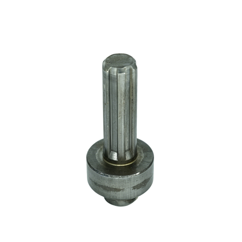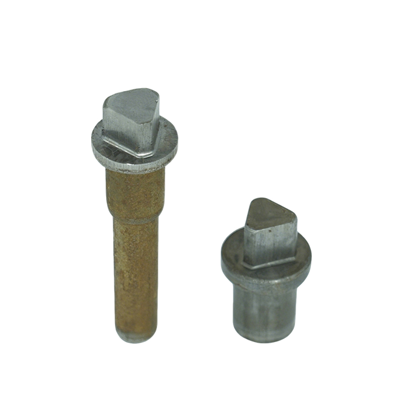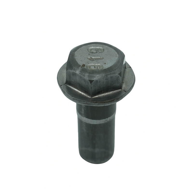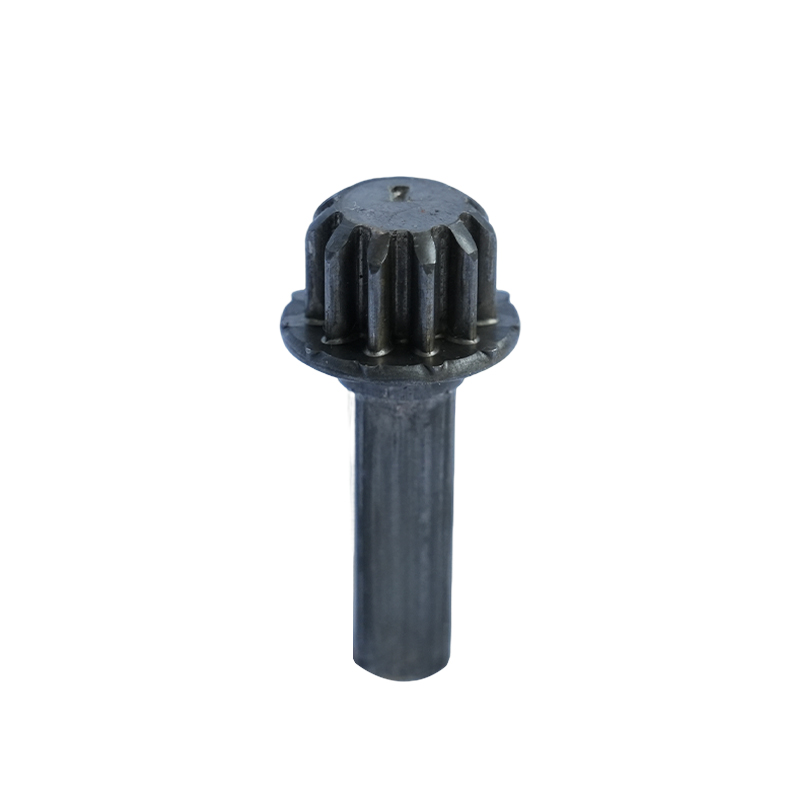

A custom bolt can look complete on a CAD screen and still be incomplete from a manufacturing perspective.
The drawing may show the overall length, thread and head shape clearly, yet leave critical questions unanswered:
How does the bolt locate in the assembly?
Which diameter actually controls fit?
Does the thread requirement apply before or after coating?
Can the head geometry be cold formed reliably?
Does the selected material have enough formability for the required shape?
Will heat treatment change a critical shoulder dimension?
And which tolerances really need to be as tight as the drawing shows?
These questions matter because a custom bolt design becomes expensive to change once tooling has been manufactured.
For engineers, buyers and sourcing teams, the best time to identify those risks is therefore before the RFQ becomes a production order.
This checklist focuses on ten areas that should be reviewed before releasing a custom bolt for tooling: function, head geometry, shoulder design, thread specification, transitions, tolerances, material, heat treatment, surface finish and the complete manufacturing route.
The goal is not to make every custom bolt simpler.
The goal is to make every feature intentional, manufacturable and measurable.
Quick Custom Bolt Design Checklist
Before sending a drawing to a custom bolt manufacturer, confirm these ten items:
- The functional role of the bolt is clearly defined
- Head diameter, height and drive geometry match the assembly
- Shoulder diameter and length are tied to actual fit requirements
- Thread size, pitch, tolerance class and thread length are specified
- Radii and transitions support both function and forming
- Critical tolerances are separated from non-critical dimensions
- Material is selected for both final performance and manufacturability
- Heat-treatment requirements and final inspection condition are defined
- Coating or finish is included in dimensional planning
- Cold heading, machining and other secondary operations are considered as one complete process
If any of these are unclear, the drawing is not necessarily wrong.
It simply means the design should receive a DFM review before tooling.
Romy’s 7 Design Rules for Reliable Cold Heading Parts provides a broader DFM framework for material flow, radii, cavities, tolerances and secondary operations in cold-formed components.
1. Start With the Function, Not the Bolt Shape
One of the most useful pieces of information a custom bolt manufacturer can receive is not another dimension.
It is an explanation of what the bolt actually does.
A custom bolt may provide more than clamping.
Depending on the product, it may also:
- Locate two components
- Maintain a controlled spacing
- Act as a pivot
- Guide movement
- Transmit torque
- Prevent rotation
- Support a bearing
- Stop at a defined axial position
- Feed through automated assembly equipment
These functions influence almost every later design decision.
Why application information changes the manufacturing review
Imagine two bolts with the same nominal dimensions.
The first is used only to clamp two brackets.
The second also acts as a pivot shaft.
The second part may require much tighter control of:
- Shoulder diameter
- Roundness
- Surface finish
- Straightness
- Shoulder length
- Concentricity
The drawing alone may not make the importance of those dimensions obvious.
By explaining the functional role, engineers help the manufacturer distinguish between:
dimensions that merely describe the shape
and
dimensions that control product performance.
Questions to answer before design freeze
Define:
- What components does the bolt mate with?
- Is the bolt stationary or moving?
- Does anything rotate on the shoulder?
- Is the fit clearance, transition or interference?
- Is clamp load important?
- Is torque transmitted through the head, shoulder or another feature?
- Is the assembly manual or automated?
- Is corrosion exposure expected?
- Will the bolt experience vibration or fatigue?
- Is the component safety-critical?
This information makes the later tolerance and manufacturing discussion much more useful.
2. Design the Head Around Installation and Material Flow
The bolt head performs several possible functions:
- Provides driver engagement
- Transfers tightening torque
- Creates a bearing surface
- Resists pull-through
- Controls installation height
- Provides anti-rotation geometry
- Supports automated feeding
For standard fasteners, established dimensional configurations already exist. ASME B18.2.1 provides dimensional requirements for several common inch-series bolt and screw head configurations.
When an existing standard head works, keeping it can simplify tooling, assembly and replacement.
A custom head becomes valuable when the standard geometry creates a specific problem.
Check head diameter
Head diameter can influence:
- Bearing area
- Pull-through resistance
- Available installation space
- Flange function
- Required material volume
- Forming severity
A larger head is not automatically better.
For cold heading, a large increase from wire diameter to head diameter requires material to move outward during upsetting.
If too much enlargement is demanded in one forming stage, risks can include:
- Buckling
- Cracking
- Incomplete filling
- Excessive tool load
Complex heads may therefore require progressive preforming across several stations.
Check head height
Head height influences:
- Driver engagement
- Installation clearance
- Material volume
- Tool strength
- Appearance
An unnecessarily thin head may create tool-support or filling challenges.
An unnecessarily tall head adds material and may interfere with surrounding components.
Check the drive feature
The drive should match:
- Required tightening torque
- Available tool access
- Automation
- Head size
- Service requirements
Possible designs include:
- External hex
- Internal hex
- Slot
- Cross recess
- Torx-style recess
- Two-flat drive
- Custom polygonal geometry
A deep internal recess can require a relatively slender punch.
That matters because the punch must survive repeated production loads.
The best drive geometry therefore balances installation performance with tool strength.
Check the bearing surface
If the underside of the head contacts another component, define whether it should be:
- Flat
- Flanged
- Radiused
- Tapered
- Serrated
- Application-specific
Do not add an integral flange simply because it looks stronger.
It should solve a measurable need such as bearing area, washer elimination or assembly stability.
3. Treat the Shoulder as a Functional Feature
The shoulder is often one of the most important features on a custom bolt.
It may act as:
- Spacer
- Bearing surface
- Locating diameter
- Pivot
- Stop
- Guide
- Structural support
Because the shoulder frequently interacts directly with another component, both its diameter and length deserve careful review.
Shoulder diameter
Ask what the shoulder actually mates with.
For example:
- Clearance hole
- Bearing
- Bushing
- Bracket
- Plastic component
- Metal housing
Do not specify the shoulder diameter in isolation.
Evaluate the mating component and the complete fit.
A dimension can meet its own drawing tolerance and still produce poor assembly if the mating part is at the opposite tolerance extreme.
Shoulder length
Shoulder length may control:
- Assembly spacing
- Axial movement
- Clamp position
- Pivot clearance
- Bearing location
A very tight shoulder-length tolerance may be justified when the feature controls an important functional stack.
If it does not, unnecessary precision can increase:
- Tooling difficulty
- Sorting
- Secondary machining
- Inspection time
Shoulder surface finish
A shoulder used only as a spacer may not need the same surface condition as one used as a rotating journal.
If another component rotates or slides on the shoulder, engineering may need to define:
- Surface roughness
- Diameter tolerance
- Roundness
- Straightness
- Hardness
- Wear resistance
In that case, a hybrid route may be appropriate: cold heading creates the overall near-net shape, while machining or grinding finishes only the functional shoulder.
Romy’s comparison of cold heading manufacturing vs CNC machining explains why combining both processes can be more efficient than forcing the entire component into either forming or machining alone.
4. Specify the Thread Completely
“Thread: M8” is not a complete thread specification.
A production-ready custom bolt drawing should clarify at least:
- Thread system
- Nominal diameter
- Pitch
- Tolerance class
- Thread length
- Thread start or lead-in
- Thread runout
- Incomplete-thread allowance
- Inspection method where important
- Coating condition
For ISO metric threads, ISO 261 provides the general plan for ISO general-purpose metric screw threads, while ISO 262:2023 specifies selected diameter-and-pitch combinations for bolts, screws, studs and nuts.
Using recognized thread combinations where possible can simplify gauges, mating hardware and global sourcing.
Define coarse or fine pitch intentionally
Do not select pitch only because it was copied from an older drawing.
Thread pitch affects:
- Thread engagement
- Adjustment resolution
- Available wall thickness
- Assembly behavior
- Manufacturing
- Mating component compatibility
The correct choice depends on the application.
Define the tolerance class
Thread size alone does not define the allowable dimensional variation.
The current ISO 965-1:2026 specifies the tolerance system for ISO general-purpose metric screw threads conforming to ISO 261.
This is especially relevant for custom bolts because coating, heat treatment and thread rolling can all influence final fit.
Specify thread length carefully
Clarify whether the drawing dimension refers to:
- Full-form thread
- Total rolled area
- Usable engagement length
- Thread including incomplete runout
This becomes particularly important near a shoulder.
A thread-rolling die needs physical room to form the thread, and incomplete threads may exist at the transition.
If full thread engagement is required immediately against a shoulder, discuss the manufacturing method before freezing the geometry.
Decide whether the thread is rolled or cut
For many cold-headed bolts, thread rolling is a logical production route.
Rolling displaces material rather than cutting it away.
The pre-roll blank diameter therefore matters because it influences:
- Pitch diameter
- Crest formation
- Rolling force
- Gauge result
For very low volume, prototypes or unusual geometry, cut threads may sometimes be more practical.
The process should match the project rather than being selected automatically.
5. Do Not Ignore Radii and Transitions
Perfectly sharp corners are easy to draw in CAD.
They are much harder to create reliably in physical metal-forming tools.
A radius can influence:
- Material flow
- Stress concentration
- Die filling
- Punch strength
- Tool wear
- Fatigue performance
This makes radii an engineering feature, not merely a cosmetic detail.
Head-to-shank transition
The underside of a bolt head experiences significant material movement during forming.
A practical radius can support smoother metal flow and reduce sharp tool edges.
If the mating component requires near-zero clearance under the head, that requirement should be discussed before tooling.
Shoulder transitions
Sudden diameter changes can create:
- Stress concentration
- Filling difficulty
- Tool stress
A practical transition may improve both manufacturing and component durability.
Do not leave important radii undefined
When one side assumes “sharp” and the other assumes “standard tool radius,” inspection disputes can occur later.
Define functionally important transitions on the drawing.
For more complex cold-heading geometry, Romy’s Cold Heading Die Design guide explains how die geometry, punch support, material flow and wear influence both tool life and finished-part accuracy.
6. Apply Tight Tolerances Only Where They Create Functional Value
A custom component does not become better simply because every dimension has a small tolerance.
Over-tolerancing is one of the easiest ways to increase the cost of custom bolts.
Tight tolerances can require:
- More precise tooling
- Frequent process adjustment
- Additional inspection
- Secondary machining
- Grinding
- Sorting
- More frequent tool maintenance
- Higher rejection risk
The most important question is:
Which dimensions actually affect the product?
Identify critical-to-function dimensions
These may include:
- Bearing diameter
- Locating shoulder
- Overall assembly length
- Thread pitch diameter
- Head bearing surface
- Anti-rotation flats
- Coaxial features
- Safety-related dimensions
These dimensions may justify tighter limits.
Allow practical variation on non-functional geometry
Examples may include:
- Clearance surfaces
- Cosmetic contours
- Non-contact radii
- Unimportant formed transitions
Giving the manufacturing process reasonable tolerance on these areas can reduce cost without affecting the application.
Think about geometric controls, not only ± dimensions
A shaft can meet diameter limits and still be:
- Bent
- Eccentric
- Misaligned
Depending on function, the drawing may need controls for:
- Straightness
- Runout
- Position
- Perpendicularity
- Profile
But geometric tolerances should also be tied to an actual functional need.
Define the final inspection condition
Is the dimension measured:
- After cold heading?
- After thread rolling?
- After heat treatment?
- After machining?
- After coating?
The answer can make a significant difference.
A design engineer and supplier should always be inspecting the same condition.
7. Select Material for Both Performance and Formability
One of the most common mistakes in custom cold-headed part design is choosing material only from the final-strength requirement.
The material also has to survive the manufacturing process.
Cold heading requires sufficient plastic deformation before the part reaches final geometry.
Important material characteristics include:
- Ductility
- Starting hardness
- Surface quality
- Chemical composition
- Wire condition
- Lubrication compatibility
Carbon and alloy steels
Carbon and alloy steels are widely used when the component requires combinations of:
- Strength
- Heat-treatment response
- Wear resistance
- Cost efficiency
For applicable metric carbon- and alloy-steel fasteners, ISO 898-1 defines mechanical and physical properties for specified property classes of bolts, screws and studs.
However, property class alone does not tell the manufacturer how severe a particular geometry can be cold formed.
The starting wire condition and forming sequence still matter.
Stainless steel
Stainless steel may be selected for corrosion resistance, appearance or environmental requirements.
But stainless grades can behave differently during cold forming because of:
- Work hardening
- Ductility
- Tool loading
- Galling tendency
A grade should therefore be reviewed for both service performance and forming behavior.
Aluminum, copper and other alloys
These materials may be appropriate when the application requires:
- Low weight
- Conductivity
- Corrosion behavior
- Specific mechanical properties
But the exact alloy and temper strongly influence manufacturability.
Do not substitute material without engineering approval
A supplier may suggest a more formable material.
That can be useful.
But a substitute should be evaluated against the original requirements for:
- Strength
- Hardness
- Corrosion
- Temperature
- Fatigue
- Wear
- Regulatory or customer standards
A manufacturing improvement is only useful if the finished component still performs correctly.
8. Define Heat Treatment Before Finalizing Critical Dimensions
Heat treatment may be necessary to achieve final:
- Strength
- Hardness
- Wear resistance
- Toughness
- Fatigue performance
But thermal processing can also influence dimensions.
Possible effects include:
- Straightness change
- Diameter change
- Distortion
- Surface condition
- Residual stress
This is especially important for:
- Long bolts
- Precision shoulders
- Bearing diameters
- Thin sections
- Components with uneven geometry
Specify hardness intelligently
A hardness requirement should reflect the application.
Over-specifying hardness can reduce toughness or create additional manufacturing risk.
Under-specifying it can result in premature wear or mechanical failure.
Decide which features are finished after heat treatment
For a precision shoulder, one possible route may be:
Cold head → heat treat → finish grind critical shoulder
rather than trying to guarantee the final precision entirely before heat treatment.
This adds an operation but may create a more stable process.
The correct approach depends on:
- Tolerance
- Geometry
- Volume
- Distortion risk
- Cost
9. Design the Coating Into the Part, Not Onto the Part
Surface treatment is often written as the final note on the drawing.
That is too late if the finish changes critical dimensions or thread fit.
Common requirements may involve:
- Zinc
- Zinc-nickel
- Phosphate
- Black oxide
- Passivation
- Electroless nickel
- Other application-specific coating systems
Coating thickness occupies dimensional space
A coating can affect:
- External thread diameter
- Internal clearances
- Press-fit diameters
- Slots
- Holes
- Shoulder fit
This is why the drawing should define whether dimensions apply:
before coating
or
after coating.
For electroplated fasteners, ISO 4042:2022 establishes requirements for electroplated coating systems on fasteners, including zinc and zinc-alloy systems and considerations related to dimensional properties and hydrogen embrittlement. The standard also has a 2026 amendment.
Consider hydrogen embrittlement risk where applicable
For high-strength steel fasteners, electroplating processes require particular attention to hydrogen embrittlement.
That does not mean every plated bolt will experience the problem.
It means the material strength, coating process and relevant specification should be reviewed together rather than treating coating as an appearance-only decision.
Define corrosion requirements by performance
Do not specify a premium coating only because “this is what we always use.”
Define:
- Service environment
- Moisture exposure
- Salt exposure
- Chemical exposure
- Desired corrosion resistance
- Appearance requirements
- Friction requirements
Then select the finish that satisfies the actual application.
10. Design the Complete Manufacturing Route Before Tooling
A custom bolt may go through many processes before it becomes a finished component.
For example:
Wire → Cutoff → Cold Heading → Thread Rolling → Machining → Heat Treatment → Coating → Inspection → Packaging
The drawing should be reviewed against the entire route.
If each stage is considered separately, late problems can appear.
Decide what should be cold formed
Cold heading can be effective for creating:
- Heads
- Flanges
- Shoulders
- Collars
- Pilot shapes
- Stepped shafts
- Certain cavities
- Near-net external geometry
Decide what should be machined
Secondary machining may be more practical for:
- Very tight local diameters
- Precise bearing journals
- Deep holes
- Cross holes
- Off-axis features
- Sharp internal features
- Certain recesses
Using machining does not mean the cold-heading design failed.
A hybrid manufacturing route can be the correct engineering answer.
Decide what should be thread rolled
Where appropriate, rolling can form the external thread after the basic blank has been cold headed.
The manufacturer must account for:
- Pre-roll diameter
- Thread length
- Runout
- Shoulder clearance
- Coating
- Final gauge condition
Think about inspection before making a dimension critical
Ask:
Can the supplier reliably measure this requirement?
A dimension that cannot be measured consistently will create problems even if it can theoretically be manufactured.
Potential inspection methods include:
- Micrometer
- Thread gauges
- Optical measurement
- Profile projector
- CMM
- Functional gauges
- Custom fixtures
- Roundness or runout measurement
- Hardness testing
Inspection method should reflect the function of the feature.
Custom Bolt Drawing: What Should Be Clearly Defined?
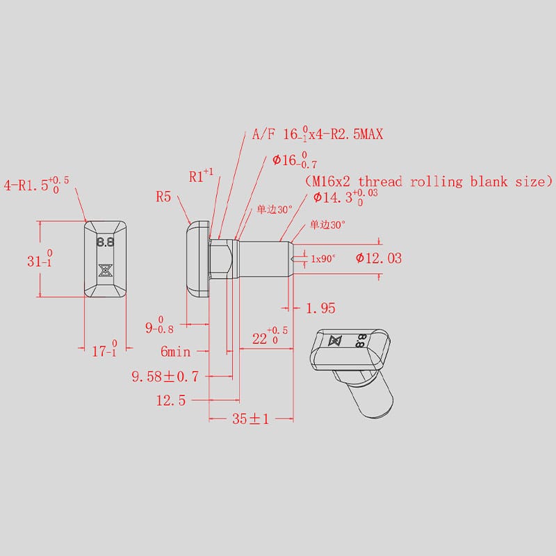
A good drawing provides enough information to eliminate avoidable assumptions.
Geometry
Include:
- Overall length
- Head diameter
- Head height
- Drive geometry
- Flange diameter where applicable
- Shoulder diameter
- Shoulder length
- Pilot dimensions
- Relevant radii
- Thread length
- Special flats or profiles
Thread
Specify:
- Thread system
- Diameter
- Pitch
- Tolerance class
- Thread length
- Runout requirement if critical
- Inspection condition
- Coated or uncoated requirement
Where appropriate, use established references such as ISO 261, ISO 262:2023 and the current ISO 965-1:2026 thread tolerance system.
Material and Mechanical Performance
Include:
- Material grade
- Strength requirement
- Hardness
- Heat treatment
- Special fatigue or wear requirements
For applicable steel bolts, screws and studs, ISO 898-1 can provide a recognized reference for specified mechanical-property classes.
Finish
Specify:
- Surface treatment
- Required corrosion performance
- Appearance where important
- Coating thickness where relevant
- Friction requirement if controlled
- Whether dimensions apply before or after finishing
For electroplated fasteners, review the applicable requirements of ISO 4042.
Quality
Where relevant, define:
- Critical characteristics
- Inspection method
- Material certification
- Dimensional report
- Traceability
- PPAP
- Capability requirements
- Special tests
Commercial Information
The drawing is not the only information a manufacturer needs.
Also provide:
- Prototype quantity
- Normal batch quantity
- Annual demand
- Lifetime volume
- Launch date
- Program duration
This helps the supplier choose a manufacturing route suitable for the entire project rather than only the first order.
A Practical Custom Bolt Design Review Table
| Design Area | Question to Ask | Risk if Ignored |
|---|---|---|
| Function | What else does the bolt do besides clamp? | Wrong critical dimensions |
| Head | Does the head fit, transfer torque and form reliably? | Tool failure or assembly interference |
| Shoulder | Is the fit based on the mating component? | Excess clearance or assembly failure |
| Thread | Are pitch, class, length and coating condition defined? | Gauge or mating problems |
| Radii | Are transitions manufacturable and functional? | Cracking, stress or tool wear |
| Tolerance | Which dimensions truly affect function? | Excess cost and inspection |
| Material | Is the material both strong enough and formable? | Cracks or poor service performance |
| Heat treatment | Are final dimensions affected? | Distortion or rejection |
| Coating | Is thickness included in fit and thread planning? | Interference or thread failure |
| Process | Are forming, machining and inspection planned together? | Late redesign and tooling changes |
Five Design Mistakes That Commonly Increase Custom Bolt Cost
1. Applying machining-level tolerances to every formed surface
This may force unnecessary secondary operations and inspection.
Better approach: Tighten only function-critical features.
2. Drawing zero-radius transitions everywhere
This can create poor material flow and fragile tool edges.
Better approach: Use the largest practical radius that still meets assembly requirements.
3. Specifying only “M8” or “M10” for the thread
This leaves pitch, tolerance class and finished condition unclear.
Better approach: Define a complete thread specification using an applicable standard.
4. Adding coating after tooling is already complete
The coating can change threads and critical fits.
Better approach: Include final coating condition during the DFM stage.
5. Designing the part without revealing annual volume
The manufacturer may optimize for the wrong process.
Better approach: Provide prototype quantity, annual demand and expected program life.
When Should You Keep the Bolt Standard?
Not every application benefits from a custom design.
A standard bolt is usually preferable when:
- Existing dimensions already meet the assembly
- Available head styles fit the installation space
- No locating or special shoulder function is needed
- Production quantities are small
- Design changes are frequent
- Universal replacement is important
- Multiple interchangeable suppliers are required
Customization should solve an identifiable engineering or manufacturing problem.
It should not be used simply to make a component proprietary.
When Does Cold Heading Make Sense for a Custom Bolt?
Cold heading is particularly worth evaluating when the part has:
- Repetitive medium- or high-volume demand
- Axis-based geometry
- Heads, flanges or shoulders
- Features that can be created through progressive forming
- Significant material removal if fully machined
However, volume is not the only consideration.
Geometry, material, tolerance, tooling complexity and secondary operations also influence process selection.
Romy’s article on cold heading manufacturing vs CNC machining provides a more detailed framework for comparing the two routes.
For complex non-standard geometry, Romy Custom Cold Heading Solutions show how cold forming can also be applied to sleeves, bushings, shafts, splines, polygonal parts and other precision components beyond conventional catalog fasteners.
What Should a Custom Bolt Manufacturer Review Before Tooling?
Before cutting production tooling, the engineering review should cover:
- Functional requirements
- Drawing revision
- Material and starting condition
- Head-forming severity
- Number of forming stations
- Shoulder fit
- Thread specification
- Critical tolerances
- Tool access
- Ejection
- Secondary machining
- Heat treatment
- Coating
- Inspection
- Annual volume
- Tool life
- Spare tooling strategy
The supplier should also identify which features are flexible.
A small change to:
- Radius
- Flange diameter
- Shoulder tolerance
- Recess depth
- Thread runout
- Coating allowance
can sometimes remove an entire secondary operation or make the forming sequence substantially more stable.
The best time to make that change is before the production tools exist.
Frequently Asked Questions
What information is needed to design a custom bolt?
At minimum, define the bolt’s function, head geometry, overall length, shoulder dimensions where applicable, thread specification, material, critical tolerances, heat treatment, finish and expected production volume.
Application information about mating parts, load, movement and environment can also help the manufacturer optimize the design.
How do I specify a metric thread on a custom bolt?
Specify the nominal diameter, pitch, thread tolerance class, required thread length and finished condition. Applicable ISO references include ISO 261 for the general metric thread plan and ISO 965-1:2026 for the general-purpose metric thread tolerance system.
Does a custom bolt need a custom thread?
No.
In many projects, keeping a standard thread while customizing the head, shoulder, flange or pilot is preferable because it preserves compatibility with existing nuts, gauges and assembly tools.
Can a custom shoulder bolt be cold headed?
Often yes, depending on geometry, material, tolerance and production volume.
The main shoulder and head may be cold formed, while extremely precise functional diameters may be calibrated, machined or ground afterward.
How tight can custom bolt tolerances be?
There is no single universal value.
Capability depends on feature size, geometry, material, forming sequence, tool wear, heat treatment, coating and inspection method.
Critical dimensions should be reviewed individually rather than applying the same tolerance philosophy to the whole component.
Should coating thickness be included in the bolt drawing?
Yes when the coating can affect threads, fits, sealing surfaces or assembly clearances.
The drawing should define whether relevant dimensions apply before or after coating.
For electroplated fasteners, ISO 4042:2022 provides requirements covering electroplated coating systems and related dimensional considerations.
What material is best for a custom bolt?
There is no single best material.
Selection depends on strength, corrosion resistance, temperature, fatigue, wear, cost and manufacturability.
For cold-headed parts, the starting material must also have suitable ductility and condition for the intended forming severity.
Should I design the bolt before contacting the manufacturer?
The basic product design should exist, but it is usually better to involve the manufacturer before every detail is frozen.
Early DFM can identify difficult forming features, unnecessary tolerances, coating allowances and possible secondary operations before tooling becomes expensive to change.
What is the advantage of designing a custom bolt for cold heading?
For suitable geometry and production volume, cold heading can create much of the part near net shape with efficient material use and repeatable production.
It can be especially useful for integrating heads, shoulders, flanges and other functional geometry into one component.
What should I send to Romy for a custom bolt review?
Provide:
- Controlled 2D drawing
- 3D model where available
- Material specification
- Functional explanation
- Critical dimensions
- Thread requirements
- Heat treatment
- Surface finish
- Annual demand
- Typical order quantity
- Quality-document requirements
A Better Custom Bolt Starts Before the Tool Is Built
The most expensive custom bolt design problem is often not a dramatic engineering failure.
It is a small requirement discovered too late.
A shoulder tolerance that should have been relaxed.
A coating allowance that was not included.
A recess that makes the forming punch unnecessarily fragile.
A thread runout that conflicts with the shoulder.
A material selected for strength but not for formability.
A critical dimension that cannot be inspected consistently.
Each of these problems is easier to solve before tooling.
A strong custom bolt design therefore connects five things from the beginning:
Function → Geometry → Material → Manufacturing → Inspection
When those five are aligned, the manufacturer can build tooling around a stable engineering definition instead of correcting problems after sampling.
If you are developing a non-standard bolt, shoulder bolt, flanged fastener or another drawing-based precision component, explore Romy Custom Cold Heading Solutions or send your drawing and production requirements to Romy for a manufacturability review before tooling begins.