
Table of Contents
Introduction
Cold heading is often associated with conventional bolts, screws and rivets, but modern multi-station forming equipment can produce much more complex geometry.
Flanges, stepped shafts, hollow sections, shoulders, recesses, polygonal profiles and other functional features can often be formed directly or near-net shape when the material and tooling strategy are suitable.
The important question is therefore not simply whether a part looks complicated.
A more useful question for a cold headed parts manufacturer is:
How must the material move to create the final geometry, and can that movement remain stable during mass production?
Two components that appear equally complicated on a drawing can have very different forming difficulty. A large flange may require several controlled upsetting stages, while a complex-looking external profile may be relatively straightforward if the material flows naturally into the die.
Understanding these limits helps engineers decide which features should be cold formed, which should be modified during DFM, and which are better completed by secondary machining.
What Geometry Can Cold Heading Produce?
Cold heading works by redistributing material through punches and dies rather than removing large amounts of metal.
Depending on the part, tooling and forming sequence, the process can create features such as:
- Enlarged heads
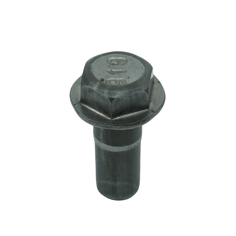
- Flanges
- Shoulders
- Stepped diameters
- Long shafts
- Pilot sections
- Hollow sleeves
- Recesses
- Internal cavities
- Polygonal profiles
- Flats
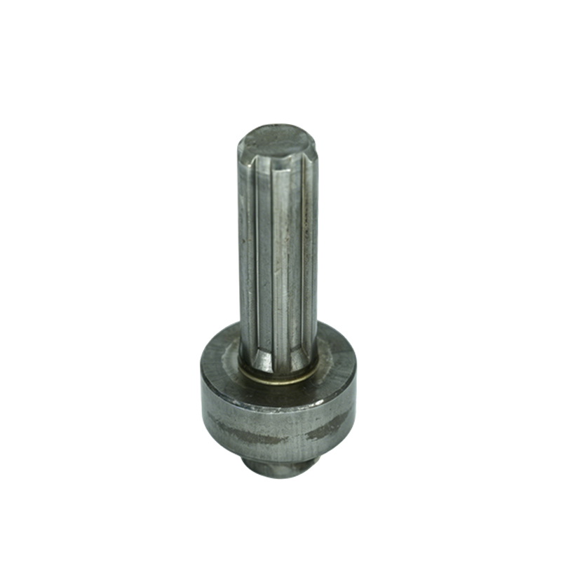
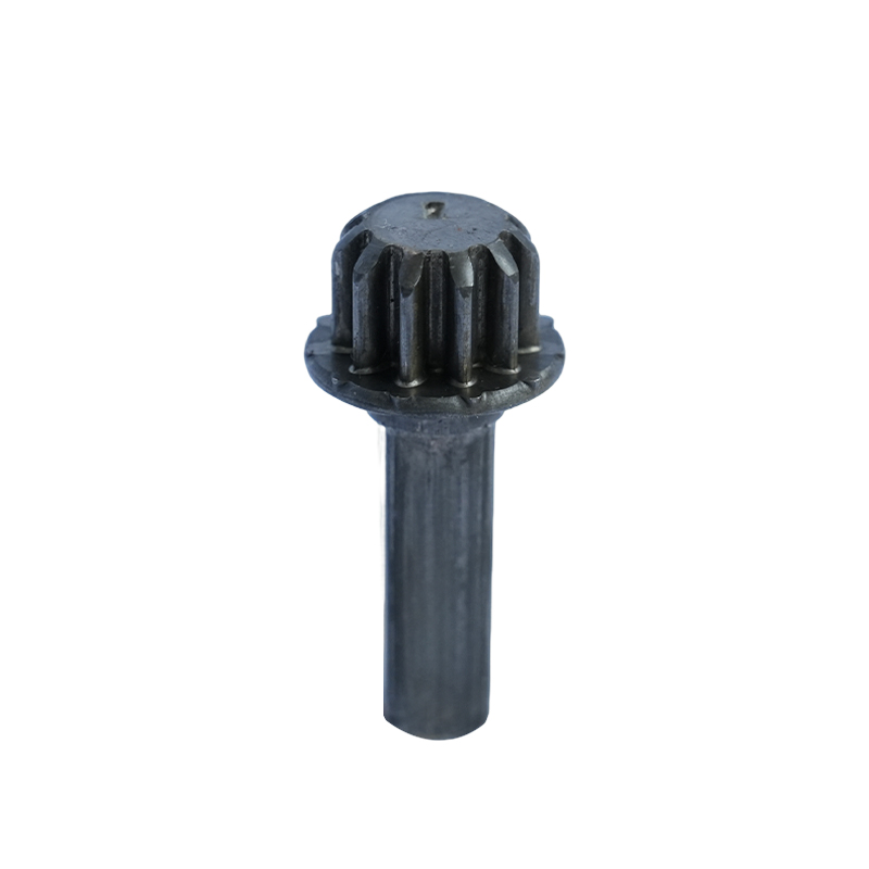
- Splines
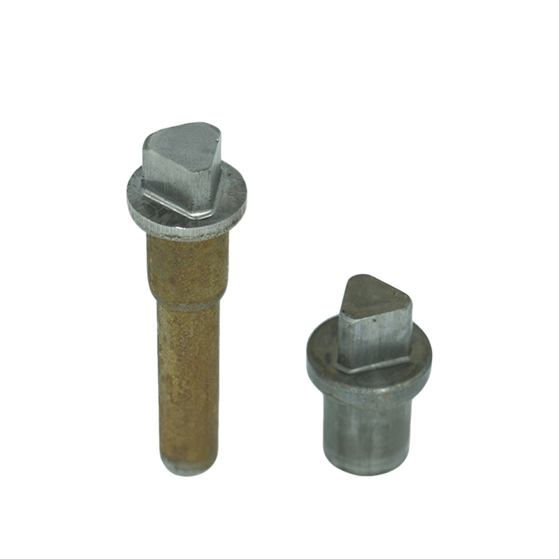
- Special-shaped external sections
This makes the process useful for much more than conventional catalog fasteners.
Romy’s Custom Cold Heading Solutions include drawing-based sleeves, bushings, special-shaped shafts, spline components, polygonal parts and other precision cold-headed geometries.
The manufacturing feasibility of each feature still depends on material, dimensions, forming severity and production volume.
1. Large Heads and Flanges Need Controlled Material Flow
A large head or flange is created by moving material outward from the original wire diameter.
The greater the difference between the starting diameter and final head diameter, the more demanding this deformation becomes.
Trying to create a very large flange in a single operation can increase the risk of:
- Buckling
- Cracking
- Incomplete filling
- Excessive tool load
- Unstable dimensions
A multi-station process can divide that deformation into several controlled steps.
For example, the sequence may progress through:
Cutoff → Preform → Intermediate Upset → Final Flange
This allows the material to gradually reach its final shape.
Larger does not automatically mean impossible
A large flange may still be suitable for cold heading if the manufacturer can control:
- Material volume
- Upsetting sequence
- Tool support
- Radii
- Lubrication
- Material ductility
This is why head-to-shank or flange-to-shank relationships should be reviewed during DFM rather than judged only by appearance.
2. Stepped Shafts Are Often Well Suited to Cold Forming
Many custom components use several diameters along the same axis.
Examples include:
- Motor shafts
- Valve components
- Locating pins
- Mechanical adjustment parts
- Automotive shafts
- Pivot components
Cold heading can often create these stepped sections through upsetting and extrusion.
The process may redistribute material to create:
- Larger shoulders
- Reduced shaft sections
- Locating diameters
- Pilot ends
The important issue is how much deformation occurs between each diameter.
A gradual sequence is generally easier to control than several severe diameter changes occurring simultaneously.
Functional diameters may still need finishing
Cold heading can create much of the geometry near net shape, but a bearing journal or other precision interface may require tighter control.
In that case, a practical route may be:
Cold Heading → Heat Treatment → Precision Machining or Grinding
This does not reduce the value of cold heading.
The forming process creates most of the geometry efficiently, while secondary machining is concentrated only where higher precision is functionally required.
3. Hollow Parts Are Possible, but Hole Geometry Matters

Cold heading is also capable of producing hollow or partially hollow components.
Examples include:
- Sleeves
- Bushings
- Tubular sections
- Axial recesses
- Blind cavities
These features are often created through backward or forward extrusion rather than drilling away all of the internal material.
However, cavity design strongly affects manufacturability.
Important variables include:
- Hole diameter
- Hole depth
- Bottom thickness
- Wall thickness
- Corner radius
- Material
- Punch slenderness
Deep and narrow cavities increase tooling difficulty
As a cavity becomes deeper and narrower, the forming punch becomes more demanding.
A long, thin punch can experience greater:
- Compression
- Bending risk
- Wear
- Breakage risk
This means a small change in hole depth or internal radius can sometimes create a significant improvement in tool life.
The engineering team should therefore identify whether the full cavity depth is functionally necessary.
4. Shoulders Can Combine Several Functions
A shoulder may appear simple, but it can perform several jobs within an assembly.
It may:
- Locate another component
- Maintain spacing
- Act as a pivot
- Provide a bearing surface
- Limit insertion depth
- Guide movement
Cold heading can often integrate this shoulder directly into the component.
This can reduce the need for separate:
- Spacers
- Sleeves
- Washers
- Locating pins
However, the required shoulder tolerance matters.
A shoulder used only for spacing may be produced directly during forming, while a shoulder functioning as a precision bearing journal may require secondary finishing.
The most efficient process therefore depends on the actual function of the feature.
5. Polygonal and Special-Shaped Profiles Can Be Formed
Cold heading does not always produce round geometry.
With suitable dies, custom components can incorporate:
- Flats
- Square sections
- Hexagonal sections
- Polygonal profiles
- Anti-rotation features
- Special external shapes
These geometries can be useful when the component must transfer torque or prevent rotation inside another part.
A formed anti-rotation feature may eliminate a secondary milling operation or a separate locking component.
The manufacturer still needs to evaluate:
- Corner filling
- Material flow
- Tool stress
- Ejection
- Final tolerance
Very sharp corners can increase forming difficulty, so practical radii are often important.
Romy’s guide to cold heading die design explains how punch and die geometry, stress concentration and tool support affect both tool life and dimensional stability.
6. Splines and Functional Profiles Need Careful DFM
Spline shafts and similar profiles are good examples of geometry that may look more suitable for machining but can sometimes benefit from forming.
A spline may be used to:
- Transfer torque
- Maintain angular position
- Engage another component
- Prevent relative rotation
For repetitive production, creating much of this geometry through forming can reduce material removal.
However, the feasibility depends on:
- Spline size
- Number of teeth
- Tooth depth
- Required accuracy
- Material
- Shaft dimensions
- Mating requirements
Some applications may use cold forming for the main shaft geometry and another process for final spline calibration or finishing.
The objective is not to force every feature into one manufacturing method.
It is to create the most stable process route for the complete part.
7. Material Can Determine Whether the Same Geometry Is Easy or Difficult
Geometry cannot be evaluated separately from material.
A shape that forms reliably in a ductile carbon steel may behave differently in stainless steel or another alloy.
Important properties include:
- Ductility
- Starting hardness
- Work hardening
- Surface condition
- Chemical composition
- Wire condition
The current ISO 4954-1:2024 specifies technical delivery requirements for non-alloy and alloy steels intended for cold heading and cold extruding.
For stainless grades, ISO 4954-2:2024 covers stainless steels supplied for cold heading and cold extruding.
These standards reinforce an important manufacturing principle: the starting material condition is part of the forming process, not simply a line item on the drawing.
Stainless steel can require a different strategy
Some stainless steels work-harden rapidly during deformation.
Depending on geometry, the manufacturer may need to adjust:
- Number of forming stages
- Deformation per station
- Lubrication
- Tooling
- Process speed
Therefore, the same CAD geometry should not automatically be assumed to have the same forming difficulty in every material.
8. Sharp Corners Are Often More Difficult Than Smooth Transitions
CAD allows designers to create perfectly sharp internal and external corners.
Metal forming is less forgiving.
Very sharp transitions can increase:
- Material-flow resistance
- Stress concentration
- Tool stress
- Crack risk
- Tool wear
A practical radius can often make forming significantly more stable.
This is particularly important around:
- Head-to-shank transitions
- Shoulders
- Flanges
- Cavity bottoms
- Diameter changes
A radius should still respect the functional requirements of the mating components.
The goal is not simply to make every corner large.
It is to avoid unnecessary sharp geometry where it provides no functional advantage.
Romy’s DFM design rules for cold heading parts provide additional guidance on radii, wall thickness, holes, material flow and dimensional requirements.
9. Very Tight Tolerances Can Change the Best Manufacturing Route
A feature may be easy to form geometrically but difficult to maintain within a very tight tolerance.
This is an important distinction.
Cold heading can create highly repeatable parts, but the final achievable tolerance depends on factors including:
- Feature geometry
- Material
- Tool design
- Tool wear
- Heat treatment
- Coating
- Measurement method
A formed diameter used only for clearance may not need the same precision as a diameter that fits a bearing.
For shaft and hole relationships, the current ISO 286-1 provides the ISO system for tolerances, deviations and fits for linear sizes.
The most useful design approach is to identify the dimensions that truly control function and concentrate process capability there.
If one diameter requires exceptional precision, it may be more efficient to finish that single diameter after cold heading instead of applying machining-level tolerance expectations to the entire component.
When Does Secondary Machining Make Sense?
Secondary machining should not be viewed as a failure of cold heading.
For many complex components, the optimum process combines both technologies.
Cold heading can create the main geometry efficiently, while CNC machining is reserved for features that genuinely need material removal.
Typical examples include:
- Cross holes
- Off-axis holes
- Very deep holes
- Precision bearing journals
- Special slots
- Sharp local geometry
- Extremely tight local tolerances
A typical hybrid route might be:
Cold Heading → CNC Finishing → Heat Treatment → Surface Treatment → Final Inspection
Compared with machining the entire component from bar stock, this approach can preserve the material and productivity advantages of near-net-shape forming while still achieving demanding local features.
How a Manufacturer Evaluates Complex Geometry
Before tooling, a cold headed parts manufacturer should review the complete drawing rather than simply deciding whether each feature is theoretically possible.
A practical DFM review considers:
| Design Area | Key Question |
|---|---|
| Head or flange | How much material must move outward? |
| Stepped shaft | How severe are the diameter changes? |
| Hollow section | Can the punch and wall geometry remain stable? |
| Shoulder | Is the feature structural, locating or precision-bearing? |
| Special profile | Can the die fill reliably and release the part? |
| Material | Can the alloy tolerate the required deformation? |
| Radius | Are transitions practical for material flow and tooling? |
| Tolerance | Can the forming process maintain the functional requirement? |
| Volume | Does dedicated tooling make sense for the production program? |
| Secondary features | Which operations are better machined afterward? |
This review should happen before the production tool is finalized.
A small adjustment to a radius, cavity depth or shoulder tolerance may remove an entire secondary process or improve tool life substantially.
What Geometry Should You Send for DFM Review?
A useful project package should include:
- Controlled 2D drawing
- 3D model where available
- Material specification
- Heat treatment
- Surface treatment
- Critical dimensions
- Mating-part information
- Annual volume
- Expected program life
- Functional explanation
Do not hide the application from the manufacturer when the geometry is complex.
Knowing that a shoulder supports a bearing or that a polygonal section transfers torque helps the engineering team distinguish between dimensions that can change and dimensions that must remain fixed.
Conclusion
Cold heading is capable of producing far more than simple screws and bolts.
With appropriate tooling and material, the process can create:
- Large heads and flanges
- Stepped shafts
- Hollow sleeves
- Precision shoulders
- Polygonal sections
- Splines
- Recesses
- Other application-specific geometry
The practical limit is rarely determined by complexity alone.
Manufacturers must evaluate how much material must move, how many forming stages are needed, whether the material can tolerate the deformation, how tooling will be loaded and which dimensions truly require secondary finishing.
The best custom cold-headed component is therefore not necessarily the part with the simplest geometry.
It is the part whose geometry, material, tooling and production requirements have been designed to work together.
For drawing-based shafts, sleeves, bushings, splines and other special-shaped components, explore Romy Custom Cold Heading Solutions or send your drawing to Romy for a cold heading feasibility review.
Frequently Asked Questions
How complex can cold headed parts be?
Modern multi-station cold heading can produce heads, flanges, shoulders, stepped shafts, cavities, sleeves, polygonal sections and other complex features. Feasibility depends on material flow, dimensions, tooling, tolerances and production volume rather than appearance alone.
Can hollow parts be produced by cold heading?
Yes. Hollow and partially hollow components can often be produced through extrusion. Hole depth, wall thickness, material and punch geometry need to be evaluated carefully during tooling design.
Can splines or non-round profiles be cold formed?
Some spline, polygonal and anti-rotation profiles can be produced or near-net formed using appropriate tooling. Required accuracy and geometry determine whether calibration or secondary finishing is also needed.
When should CNC machining be used after cold heading?
Secondary machining is useful for cross holes, off-axis features, precision bearing surfaces, deep holes and very tight local tolerances that are inefficient to create entirely through forming.
What information does a cold headed parts manufacturer need for DFM?
Provide a 2D drawing, 3D model where available, material, critical dimensions, heat treatment, surface finish, annual volume and information about how the part functions inside the final assembly.
Need Help Evaluating a Complex Cold-Headed Part?
If your component includes unusual flanges, shoulders, cavities, splines, polygonal profiles or other non-standard geometry, an early DFM review can determine which features should be cold formed and which should use secondary processing.
Send your drawing and application requirements to Romy for a manufacturability review before tooling begins.