
Table of Contents
Introduction
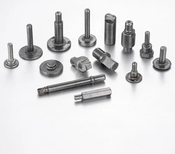
Cold heading can produce highly repeatable components at scale, but the process depends on controlled material flow, suitable raw material, stable tooling and correct machine setup.
When one of these conditions moves outside the acceptable process window, defects can appear.
Common examples include surface cracks, laps or folds, incomplete filling, eccentric geometry and dimensional drift. Some problems are immediately visible, while others appear only during measurement, assembly or later finishing.
For engineers and buyers working with cold headed parts, understanding these defects is useful because the visible symptom does not always reveal the true root cause.
A crack may originate from material condition, excessive deformation or an unsuitable radius. An underfilled flange may result from insufficient blank volume, poor preform design or tool wear. A dimensional problem may come from the tool rather than the machine.
The purpose of defect analysis is therefore not simply to reject a bad part. It is to determine which combination of material, tooling and process conditions created the problem and prevent it from repeating.
Why Cold Heading Defects Occur
Cold heading reshapes metal through plastic deformation rather than removing material.
The starting wire contains a controlled volume of metal, and the punches and dies progressively redistribute that volume into the required geometry.
For cold heading to remain stable, several elements must work together:
- Raw material condition
- Blank volume
- Forming sequence
- Punch and die geometry
- Lubrication
- Machine alignment
- Tool condition
- Process setup
- Inspection frequency
Current ISO 4954-1:2024 specifies technical delivery requirements for non-alloy and alloy steels intended for cold heading and cold extruding, reinforcing the importance of controlling the starting material rather than evaluating only the finished component.
Romy’s cold heading DFM design guide also explains how material flow, radii, cavity geometry, tolerances and downstream operations affect the stability of cold-headed components.
1. Cracks
Cracking is one of the most recognizable cold-heading defects.
A crack forms when local deformation exceeds the material’s ability to deform without fracture.
It may appear around:
- Head-to-shank transitions
- Flange edges
- Deep recesses
- Shoulder transitions
- Extruded sections
- Highly deformed surfaces
What causes cracks?
Possible causes include:
- Insufficient material ductility
- Excessive deformation in one forming station
- Sharp radii
- Surface defects in the incoming wire
- Excessive work hardening
- Poor lubrication
- Tool misalignment
- Incorrect material condition
The same geometry may form successfully in one material and crack in another because different materials have different ductility and work-hardening behavior.
How can cracking be reduced?
A manufacturer may adjust:
- Preform geometry
- Number of forming stages
- Transition radii
- Material condition
- Lubrication
- Tool alignment
- Deformation distribution
For severe geometry, splitting one large deformation into several progressive stages can reduce localized strain.
This is one reason complex cold-headed parts should be reviewed through DFM before tooling is finalized.
2. Laps and Folds
A lap occurs when material folds over itself during forming and the folded surface becomes trapped in the finished component.
Unlike a simple external scratch, a lap is created by the material-flow pattern itself.
Laps may appear around:
- Flanges
- Heads
- Shoulders
- Large diameter transitions
- Complex preforms
ASM International’s technical literature on failure in steel forging discusses forging discontinuities including flow-related defects, laps and cracks, together with the influence of lubrication, tooling and process design.
Common causes of laps
Possible causes include:
- Poor preform geometry
- Excessive material in a local area
- Unstable upsetting
- Incorrect blank volume
- Sharp die transitions
- Material flowing in conflicting directions
Imagine a large flange that requires significant material redistribution.
If the preform does not guide the metal correctly, material from different directions can meet and fold rather than fill the die cavity smoothly.
Prevention begins with material-flow design
Correcting a lap may require more than adjusting machine pressure.
The manufacturer may need to modify:
- Blank size
- Preform shape
- Station sequence
- Die radius
- Material distribution
This is why cold-heading tooling should be designed as a progressive material-flow system rather than simply as a negative copy of the final CAD geometry.
Romy’s article on cold heading die design explains how punch geometry, die design and material flow influence both tooling life and finished-part consistency.
3. Underfill or Incomplete Filling
Underfill occurs when material does not completely fill the intended die cavity.
The finished part may show:
- Incomplete flange edges
- Rounded corners where sharper geometry was expected
- Partially formed head features
- Incomplete recess geometry
- Short external profiles
This does not always mean there was simply “not enough pressure.”
Common causes of underfill
Possible causes include:
- Insufficient blank volume
- Poor material distribution
- Incorrect cutoff length
- Inadequate preform geometry
- Tool wear
- Excessive friction
- Poor lubrication
- Incorrect machine adjustment
Cold heading follows volume conservation.
The metal needed to create the final head, flange, shoulder or other feature must already exist in the starting blank and must be directed into the correct area during forming.
If too little material reaches a particular feature, the die cannot fill properly.
Why adding more material is not always the answer
Increasing blank volume without understanding the flow path can create a different defect.
Excessive material may lead to:
- Folding
- Flash
- Tool overload
- Length variation
The objective is not maximum material.
It is correct material distribution.
4. Dimensional Drift
A cold-headed part may begin a production run within specification and gradually move toward a tolerance limit.
This is dimensional drift.
It is particularly important in long production runs because the process may initially appear completely stable.
Dimensions affected can include:
- Shaft diameter
- Head diameter
- Head height
- Shoulder position
- Recess depth
- Overall length
- Profile dimensions
Tool wear is a common reason
Punches, dies and inserts experience repeated mechanical contact during every forming cycle.
As surfaces wear, the geometry transferred to the finished part can change gradually.
For this reason, long-run production should not rely only on first-piece inspection.
Critical characteristics may need periodic measurement throughout the production batch.
Dimensional drift can also come from other sources
Possible causes include:
- Material-lot variation
- Machine alignment
- Temperature changes
- Lubrication condition
- Tool movement
- Cutoff-length variation
The objective of process control is to detect the trend before the part becomes nonconforming.
5. Eccentricity and Misalignment
A cylindrical part may meet its diameter requirement and still be functionally incorrect if its features are not aligned.
Examples include:
- Head not centered on the shaft
- Hole not centered with the external diameter
- Stepped diameters not sharing the same axis
- Recess misaligned with the shaft
- Uneven wall thickness
These problems can be particularly important in:
- Shafts
- Sleeves
- Bushings
- Motor components
- Valve components
- Rotating parts
What can cause eccentricity?
Potential causes include:
- Punch and die misalignment
- Tool wear
- Uneven material flow
- Incorrect blank positioning
- Machine alignment
- Poorly supported tooling
For precision components, inspection may therefore need to consider more than diameter.
Depending on function, engineers may need to evaluate:
- Runout
- Position
- Straightness
- Wall thickness
- Concentric feature relationships
Romy’s precision fastener tolerance guide explains why functional relationships between features can be more important than simply tightening every ± dimension.
6. Surface Damage and Tool Marks
Some cold-headed parts show surface defects even when their overall dimensions remain acceptable.
Examples include:
- Scratches
- Scoring
- Galling
- Tool marks
- Surface tearing
Potential causes can include:
- Poor lubrication
- Contaminated material
- Worn tool surfaces
- Excessive friction
- Damaged dies
- Material surface defects
The importance of these marks depends on where they occur.
A cosmetic mark on a non-contact area may be less important than a defect on:
- Sealing surface
- Bearing area
- Thread
- Fatigue-critical transition
- Visible customer-facing surface
Inspection requirements should therefore reflect the function of the surface rather than treating every mark identically.
7. Straightness Problems in Long Parts
Long cold-headed shafts and rod-like components introduce another manufacturing challenge: straightness.
A part can meet its diameter and length requirements while still bending enough to cause assembly problems.
Potential causes include:
- Uneven forming load
- Tool misalignment
- Ejection forces
- Heat treatment
- Residual stress
- Handling after forming
For a long component that rotates, passes through a guide or enters several aligned holes, straightness can become a critical characteristic.
In these cases, the manufacturing plan may include:
- Process adjustment
- Straightness inspection
- Post-heat-treatment inspection
- Straightening where appropriate
- Secondary finishing
The final acceptance stage should match the condition in which the part will actually be used.
Material Problems vs Process Problems
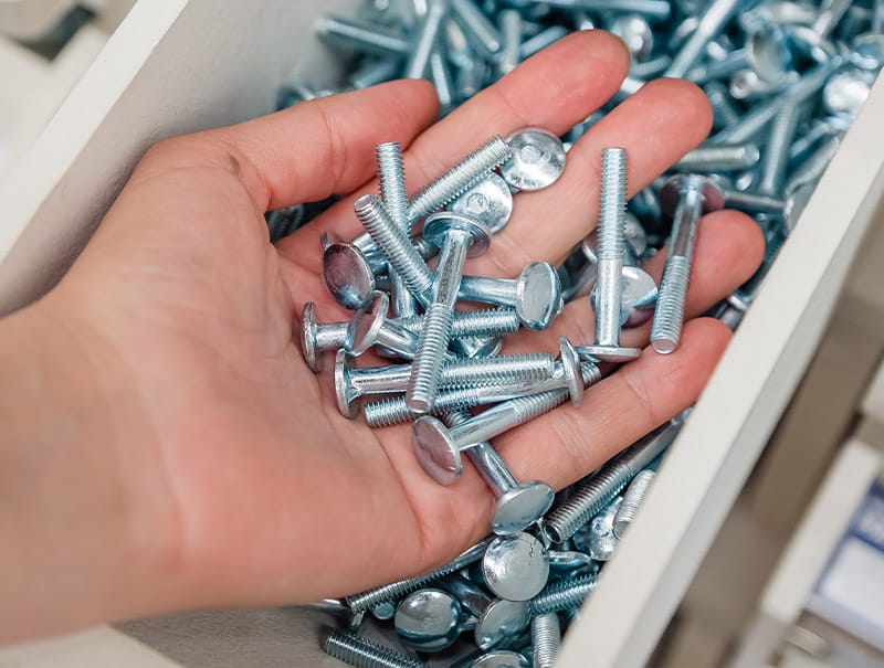
When a defect appears, the first challenge is determining where it originated.
A useful starting framework is:
| Defect | Possible Material Cause | Possible Process/Tooling Cause |
|---|---|---|
| Crack | Low ductility, surface defect | Excessive deformation, sharp radius |
| Lap | Usually indirect | Poor material flow or preform |
| Underfill | Incorrect wire/cutoff condition | Poor volume distribution, worn tool |
| Dimensional drift | Lot variation | Tool wear, setup movement |
| Eccentricity | Wire variation possible | Alignment or uneven flow |
| Surface damage | Wire surface problem | Lubrication or damaged tooling |
| Straightness issue | Material/residual stress | Forming alignment or heat treatment |
This table is a diagnostic starting point rather than a universal root-cause chart.
Multiple factors can create similar visible symptoms.
Reliable diagnosis requires reviewing the process data, tooling condition and material together.
How DFM Helps Prevent Defects Before Production
The most efficient time to solve a cold-heading defect is before the production tool is built.
DFM allows engineers to evaluate:
- Forming severity
- Head-to-shank relationship
- Flange size
- Radii
- Cavity depth
- Wall thickness
- Extrusion ratios
- Material
- Tolerances
- Secondary operations
For example, changing a very sharp shoulder to a practical radius may improve material flow and reduce tool stress.
Reducing an unnecessarily deep cavity may allow a stronger punch.
Relaxing a non-critical tolerance may remove a secondary finishing operation.
A strong DFM review does not simplify the product blindly.
It protects the functional requirements while creating a wider and more stable manufacturing window.
How Manufacturers Control Defects During Mass Production
Even a good design still requires production control.
A practical cold-heading quality system can include:
Incoming material control
Verify relevant characteristics such as:
- Material grade
- Wire diameter
- Surface condition
- Material certification
- Lot identification
First-piece inspection
Confirm that machine setup and tooling produce acceptable parts before full production begins.
In-process inspection
Monitor critical dimensions during the run rather than relying only on final inspection.
Tool-life monitoring
Track wear on punches, dies and inserts that influence critical dimensions.
Final inspection
Confirm the finished condition after relevant secondary processes such as:
- Heat treatment
- Machining
- Thread rolling
- Surface treatment
Traceability
Where required, maintain links between finished parts and:
- Material batch
- Production batch
- Tooling
- Heat treatment
- Surface treatment
- Inspection results
For drawing-based components, Romy’s Custom Cold Heading Solutions combine tooling development, cold heading, secondary processing and quality inspection for non-standard parts.
What Should Buyers Ask When a Defect Appears?
A useful supplier discussion should go beyond:
“Why is this part defective?”
Ask instead:
Where did the defect first appear?
Was it present:
- Immediately after forming?
- After heat treatment?
- After machining?
- After coating?
Is the defect random or progressive?
A progressive dimensional change may indicate tool wear.
Random defects may point toward material, feeding or process instability.
Is the problem limited to one batch?
Compare:
- Material lots
- Tooling history
- Machine setup
- Secondary-process batches
What corrective action changes the root cause?
Sorting bad parts removes defective output.
It does not necessarily fix the process.
A complete corrective action should identify why the problem appeared and what prevents recurrence.
Conclusion
Cold heading defects are rarely caused by one factor in isolation.
Reliable production depends on the interaction between:
- Material
- Geometry
- Forming sequence
- Tooling
- Lubrication
- Machine setup
- Secondary processing
- Inspection
Cracks often point toward excessive local deformation or material limitations. Laps usually indicate an unstable flow path. Underfill suggests that material is not reaching the required area correctly. Dimensional drift may reveal tooling wear or process variation.
The most effective quality strategy is therefore not simply detecting defective parts at final inspection.
It is designing a stable process that prevents defects from developing in the first place.
For non-standard shafts, sleeves, bushings, fasteners and other complex cold-headed components, Romy Custom Cold Heading Solutions support development from DFM and tooling through production and inspection.
Frequently Asked Questions
What causes cracks in cold headed parts?
Cracks can result from insufficient material ductility, excessive deformation, sharp transitions, poor lubrication, incoming material defects or incorrect tool alignment. The actual cause should be confirmed by reviewing both material and the forming process.
What is a lap defect in cold heading?
A lap is a fold created when material flows over itself during forming. It is commonly associated with unsuitable preform geometry, excessive local material or unstable material flow.
Why does underfill occur in cold heading?
Underfill occurs when material does not completely fill the die cavity. Possible causes include incorrect blank volume, poor preform design, excessive friction, tool wear or machine setup.
Why do cold-headed dimensions change during a long production run?
Tool wear is one common cause of dimensional drift, but material variation, machine alignment, lubrication and cutoff consistency can also contribute. Critical dimensions should be monitored throughout production.
Can DFM reduce cold heading defects?
Yes. DFM can identify excessive deformation, sharp radii, weak punch geometry, difficult cavities and unnecessary tolerances before tooling begins, allowing engineers to improve the process before mass production.
Need Help Solving a Cold Heading Quality Issue?
If your component is experiencing cracking, incomplete filling, dimensional instability or another forming problem, an engineering review can help determine whether the issue originates from geometry, material, tooling or the production sequence.
Send your drawing and application requirements to Romy for a cold-heading manufacturability and process review.