
Table of Contents
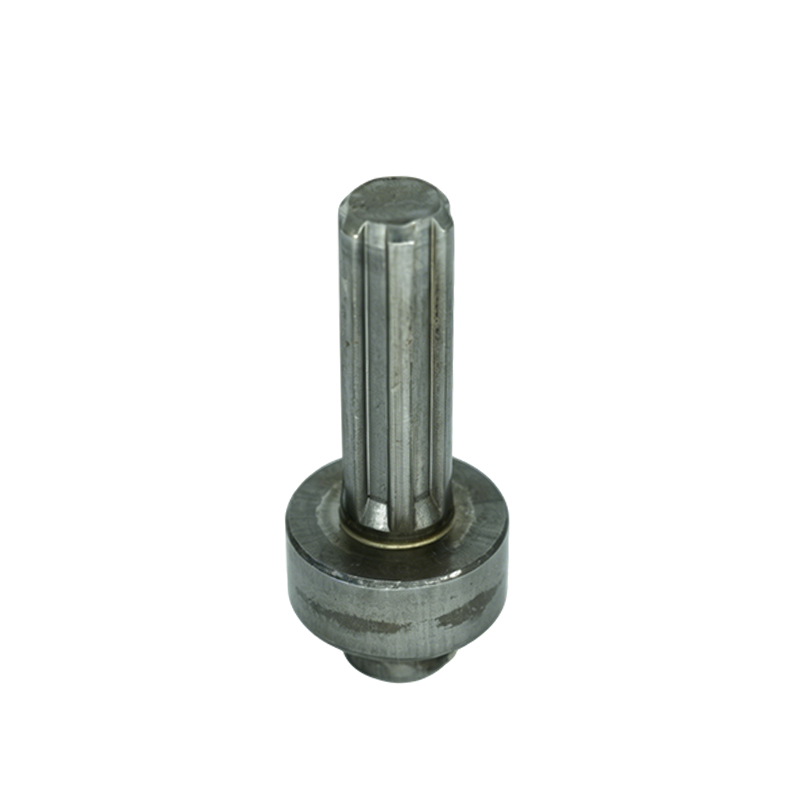
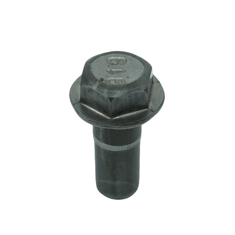
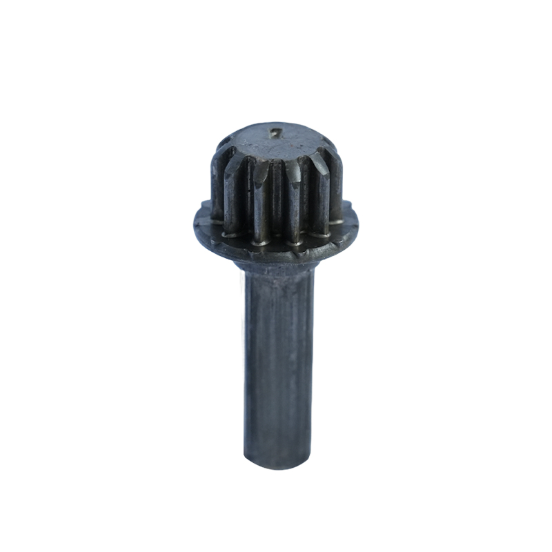
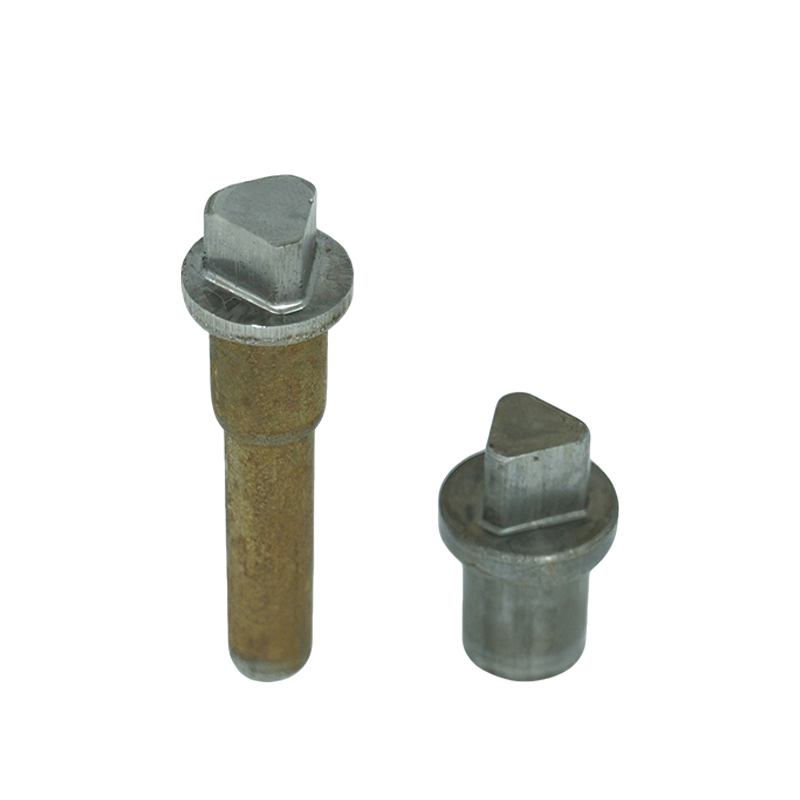
For buyers sourcing special-shaped parts, this review focuses on triangular profile fit. The component example is the elevator triangular key shaft. The first decision is which surfaces establish position and which surfaces need clearance. A dimension becomes useful only when its role in the assembly is clear.
Define the working interface for special-shaped parts
Across-corner size does not completely describe a triangular engagement profile. Corner radius, flat position and engagement depth can each affect fit. The drawing should identify the profile reference and locating shoulder while leaving operating and access procedures to the qualified elevator service organization. For special-shaped parts, start by identifying the specified elevator lock mechanism. Mark the surfaces that locate, support or transmit force and keep them distinct from clearance surfaces. This gives the supplier a functional reason for each important dimension instead of asking for equal precision everywhere.
Connect the features to a datum
Review triangular engagement section and locating flange as one geometry. The drawing should show how the features relate to a repeatable reference. If the reference exists only in the assembled product, provide enough mating information for the manufacturer to reproduce it during inspection. In the elevator key shafts example, the review therefore follows the triangular engagement section and locating flange through the drawing and the assembled position.
Separate nominal size from usable contact
The practical question for special-shaped parts is where contact occurs after full seating. Lead-ins, corner radii and transitions can reduce usable engagement without changing the envelope dimension. Review a section view and define the intended contact zone before deciding which tolerances to tighten.
Compare the available design decisions
Keep the baseline drawing beside any proposed revision. A wider clearance may simplify assembly while changing movement or contact. A tighter size may increase inspection or finishing requirements. Evaluate the change against the function it affects and record the accepted trade-off.
| Review choice | Useful evidence | Decision limit |
|---|---|---|
| Drawing dimensions | Actual results tied to datums and final condition | Does not alone validate the complete assembly |
| Functional or profile gauge | Controlled master and documented check coverage | Only proves characteristics the gauge evaluates |
| Representative assembly trial | Identified mating parts and repeatable observations | System load and life tests remain application-specific |
Evaluate the manufacturing route
For this example, the site lists 1Cr13. The material label does not establish what every version of special-shaped parts can achieve. Ask which features can be formed directly, which need another operation, and which dimensions will be verified after the final processing step. The listed material is a product-page reference for this example. Confirm the controlled specification for the actual order rather than importing the catalog's approximate grade equivalents.
Build a representative fit trial for special-shaped parts
Test special-shaped parts with a controlled mating component, identified by revision. Record entry, seating and the final operating position separately. If the trial fails, preserve the contact evidence and measurement setup so a drawing change addresses the actual interface rather than an assumed cause.

Set an approval boundary
Release the geometry with defined dimensions, references and accepted evidence. A successful hand fit is useful feedback but does not replace the specified component checks or system qualification. For special-shaped parts, preserve the approved sample alongside the drawing rather than letting either become an uncontrolled substitute.
Prepare the supplier discussion
Send the current drawing, mating envelope and the specific fit concern. For special-shaped parts, ask for a feature-by-feature feasibility response and a clear description of any proposed departure. The resulting quotation should identify the drawing revision and the condition in which the part will be supplied.
For further background, consult NIST guidance on measurement process characterization. This independent resource supports the review method; it does not certify the component or replace its approved application specification.
Discuss Your Component
To discuss special-shaped parts, send Romy the controlled drawing, mating requirements, intended material condition and expected order quantities. Identify triangular profile fit as the point requiring review, and request a written feasibility response with any process exceptions before tooling or production is released.
See the Elevator Triangular Key Shaft product example and contact Romy with the drawing revision for your project.
Frequently Asked Questions
What should be defined first for special-shaped parts?
Identify the surfaces that establish position and the mating parts that constrain them. That determines which dimensions and relationships require specific control.
Can a matching nominal size prove compatibility?
No. Profile, engagement depth, corner geometry and final surface condition can change fit even when a principal size matches.
Should every tolerance be made tighter?
No. Tighten requirements where the assembly needs them and verify the manufacturing and inspection consequences before releasing the revision.
What makes a fit trial repeatable?
Use identified mating components, a controlled assembly condition and a record of entry, seating and final position.
What should the supplier return for special-shaped parts?
A drawing-based feasibility review, identified exceptions, proposed process route and a plan for verifying the functional features.